background image

  1 6

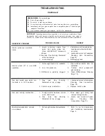
TROUBLESHOOTING

Continued

WARNING: 

If you smell gas

Shut  off  gas  supply.

Do  not try  to  light  any  appliance.

Do  not touch  any  electrical  switch;  do not use  any  phone  in  your building.

Immediately  call  your  gas  supplier  from  a  neighbor’s  phone.  Follow  the  gas

        supplier’s  instructions.

If  you  cannot  reach  your  gas  supplier,  call  the  fire  department.

IMPORTANT

:

  Operating  heater  where  impurities  in  air  exist  may  create odors. Clean-

ing supplies,  paint,  paint  remover,  cigarette  smoke,  cements  and  glues,  new  carpet  or

textiles,  etc.,  create  fumes. These fumes may mix  with  combustion  air  and  create odors.

REMEDY

1.     Ventilate room. Stop using odor
        causing products while heater
        is running.
2.     Locate and correct  all  leaks(see
        Checking     Gas     Connections,
       Page 10).
3.    Refill supply tank.

1.    Open  window  and/or  door   for
        ventilation.
2.    Contact     local    propane/LP
        gas company.
3.     Clean  ODS/pilot (see  Cleaning
         Page  13).

1.     Locate and  correct  all  leaks (see
       Checking     Gas    Connections,
        Page  10).
2.    Replace  control  valve.

1.    Take    apart    gas   tubing   and
        remove  foreign  matter.
2.     Locate    and   correct   all   leaks
       (see              Checking         Gas
        Connections,  Page 10).

1.    Refer   to  Air  for  Combustion
      and  Ventilation  requirements
        Page  4.

POSSIBLE CAUSE

1.    Heater   is  burning    vapors    from
       paint,    hair    spray,   glues,   etc.
          (See    IMPORTANT    statement
      above).
2. Gas  leak.  See  Warning  Statement
       at the top of page.
3.    Low fuel supply.

1.     Not enough  fresh  air  is  available.

2.    Low   line  pressure.

3.  ODS/pilot  is  partially  clogged.

1.    Gas      leak.      See      Warning
       Statement  at  top  of  page.

2.   Control   valve  is defective.

1.    Foreign  matter  between  control
        valve  and  burner.
2.    Gas        leak.       See      Warning
       Statement  at  top  of  page.

1.    Not enough combustion/ventilation
     air.

OBSERVED  PROBLEM

Heater  produces  unwanted
odors.

Heater    shuts    off    in    use  (ODS
operates).

Gas  odor  exists  even  when  con-
trol  knob  is  in   OFF  position.

Gas  odor  during  combustion.

Moisture/condensation  noticed
on  windows.

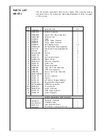
Summary of Contents for HB06ML-1

Page 1: ...structions If you cannot reach your gas supplier call the fire department Installation and service must be performed by a qualified installer service agency or gas supplier ImportantSafetyInformation 2 Product Features 3 ProperVentilation FreshAir 4 Installation 6 OperatingYour Heater 10 Cleaning Maintenance 13 Trouble Shooting 14 Specifications 17 Parts List 19 Warranty information 24 WARNING Thi...

Page 2: ...ce Never place any objects on the heater Due to high temperatures heater s h o u l d b e k e p t o u t o f traffic and away from furniture and draperies Surface of heater becomes very hot when running heater Keep children and adults away from hot surface to avoid burns or clothing ignition Heater will remain hot for a time after shut down Allow surface to cool before touching Carefully supervise y...

Page 3: ...that has complied with all the requirements of the authority having jurisdiction State of Massachsetts The installation must be made by a licensed plumber or gas fitter in the Commonwealth of Massachusetts Sellers of unvented propane or natural gas fired supplemental room heaters shall provide to each purchaser a copy of 527 CMR 30 upon sale of the unit In the state of Massachusetts unvented propa...

Page 4: ...described in the National Fuel Gas Code ANS Z223 1 Section 5 3 or applicable local codes Unusually Tight Construction The air that leaks around doors and windows may provide enough fresh air for combustion and ventilation However in buildings of unusually tight construction you must provide additional fresh air Unusually tight construction is defined as construction where a walls and ceilings expo...

Page 5: ...dd the Btu Hr of all fuel burning appliances in the space Vent free heater Btu Hr Gas water heater Btu Hr Gas furnace Btu Hr Vented gas heater Btu Hr Gas Fireplace logs Btu Hr Other gas appliances Btu Hr Total Btu Hr Do not include direct vent gas appliances Direct vent draws combustion air from the outdoors and vents to the outdoors 4 Compare the maximum Btu Hr the space can support with the actu...

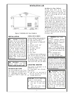
Page 6: ...G HEATER This heater is designed to be mounted on a wall For convenience and efficiency install heater where there is an easy access for operation inspection and service in coldest part of room INSTALLATION CAUTION If you install the heater in a home garage heater pilot and burner must be at least 18 inches above floor locate heater where moving vehicle will not hit it CAUTION This heater creates ...

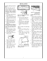
Page 7: ...een studs or to solid walls concrete or masonry Decide which method better suits your needs Either method will provide a secure hold for the mounting bracket Marking Screw Locations 1 Tape mounting bracket to wall where heater will be located Make sure mounting bracket is level 2 Mark screw locations on wall see Figure 8 Note Only mark last hole on each end of mounting bracket Insert mounting scre...

Page 8: ...gs 5 Place mounting bracket onto wall Line up last hole on each end of bracket with wall anchors 6 Insert mounting screws through bracket and into wall anchors 7 Tighten screws until mounting bracket is firmly fastened to wall Placing Heater On Mounting Bracket 1 Locate two horizontal slots on back panel of heater see Figure 11 2 Place heater onto mounting bracket Slide horizontal slots onto stand...

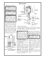
Page 9: ...d pressure regulator with wrench when connecting it to gas piping and or fittings CAUTION Use pipe joint sealant that is resistant to liquid petroleum LP gas Figure 14 Gas Connection The installer must supply an external regulator The external regulator will reduce incoming gas pressure You must reduce incoming gas pressure to between 11 and 13 inches of water If you do not reduce incoming gas pre...

Page 10: ...lve to control valve see Figure 16 Apply mixture of liquid soap and water to gas joints Bubbles forming show a leak 5 Correct all leaks at once 6 Light heater see Operating Heater pages 10 and 11 for non thermostat models or page 12 for thermostat model Check the rest of the internal joints for leaks 7 Turn off heater see To Turn Off Gas to Appliance page 11 for non thermostat models or page 12 fo...

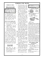
Page 11: ...rtially press down the control knob slightly and rotate counterclockwise Release the downward pressure on the knob while continuing to turn until the knob locks at the desired set ting position Do not operate between locked positions Set control knob to desired heating position NOTE Both HIGH and LOW are locked positions You must press in control knob before turning it from these positions TO TURN...

Page 12: ...t refer to Troubleshooting pages 14 through 16 Also contact a qualified service person or gas supplier for repairs Until repairs are made light pilot with match To light pilot with match see Manual Lighting Procedure 7 Keep control knob pressed in for 30 seconds after lighting pilot After 30 seconds release control knob If control knob does not pop up when released contact a qualified service pers...

Page 13: ...soap and water mixture Wipe the cabinet to remove dust INSPECTING BURNER Check pilot flame pattern and burner flame pattern often PILOT FLAME PATTERN Figure 21 shows a correct pilot flame pattern Figure 22 shows an incorrect pilot flame pattern The incorrect pilot flame is not touching thermocouple This will cause the thermocouple to cool When the thermocouple cools the heater will shut down If pi...

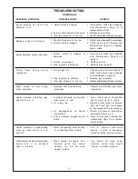
Page 14: ...g is not correct 6 Control knob not in PILOT position 7 Depleted gas supply 1 Control knob is not fully pressed in 2 Control knob is not pressed in long enough 3 Equipment shutoff valve is not fully open 4 Thermocouple connection is loose at control valve 5 Thermocouple damaged 6 Control valve damaged REMEDY 1 Replace ignitor 2 Replace ignitor 3 Reconnect ignitor cable 4 Free ignitor cable if pinc...

Page 15: ...ing while heating or contracting while cooling 1 When heated the vapors from furniture polish wax carpet cleaners etc turn into white powder residue REMEDY 1 Clean burner orifice see Cleaning and Maintenance Page 13 or replace burner orifice 2 Replace burner orifice 3 Contact local propane LPgascompany 1 Contact local propane LP gascompany 2 Clean burner see Cleaning and Maintenance Page 13 or rep...

Page 16: ...ne LP gas company 3 Clean ODS pilot see Cleaning Page 13 1 Locate and correct all leaks see Checking Gas Connections Page 10 2 Replace control valve 1 Take apart gas tubing and remove foreign matter 2 Locate and correct all leaks see Checking Gas Connections Page 10 1 Refer to Air for Combustion and Ventilation requirements Page 4 POSSIBLE CAUSE 1 Heater is burning vapors from paint hair spray glu...

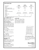
Page 17: ... from whom you purchased this product If they are unable to supply original replacement part s call the num ber on the front of this manual When contacting your dealer or HearthRite have ready your name your address model and serial numbers of your heater how heater was malfunction ing type of gas used propane LP or natural gas purchase date warranty card Usually we will ask you to return the defe...

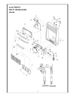
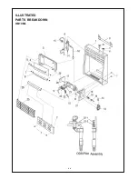
Page 18: ...1 8 ILLUSTRATED PARTS BREAKDOWN HB06ML ...

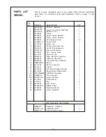
Page 19: ...084 03E ML060 02 ML083 03 MB28001 ML070 12E ML071 02 PARTS AVAILABLE NOT SHOWN DESCRIPTION Cabinet Assembly Lower Front Panel Assembly Reflector Unit Glass Upper Glass Retainer Lower Glass Retainer Self Tapping Screw Control Valve Ignitor Line Control Valve Fixed Nut Control Knob Assembly Pressure Regulator Self Locking Screw Pressure Tap Main Inlet Tube Assembly ODS Line Assembly Gas Outlet Tube ...

Page 20: ...2 0 ILLUSTRATED PARTS BREAKDOWN HB10ML ...

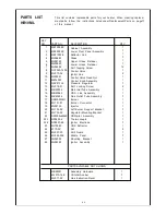
Page 21: ... ML084 03E ML060 02 ML083 03 MB28001 ML070 14E ML071 02 PARTS AVAILABLE NOT SHOWN DESCRIPTION Cabinet Assembly Lower Front Panel Assembly Reflector Unit Glass Upper Glass Retainer Lower Glass Retainer Self Tapping Screw Control Valve Ignitor Line Control Valve Fixed Nut Control Knob Assembly Pressure Regulator Self Locking Screw Main Inlet Tube Assembly ODS Line Assembly Gas Outlet Tube Assembly B...

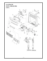
Page 22: ...2 2 ILLUSTRATED PARTS BREAKDOWN HB10TL ...

Page 23: ...83 03 MB28001 ML070 30E ML071 02 ML065 01 PARTS AVAILABLE NOT SHOWN DESCRIPTION Cabinet Assembly Lower Front Panel Assembly Reflector Unit Glass Upper Glass Retainer Lower Glass Retainer Self Tapping Screw SIT Thermostat Valve Assembly Thermostat Valve Base Bracket Nut Screws Grill Self Locking Screw Middle Panel Pressure Regulator Ignitor Line Mounting Bracket Main Inlet Tube Assembly ODS Line As...

Page 24: ...2 4 ...
Reviews: