


4
Transmitter wall clip
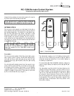
The transmitter can be hung on a wall using the clip pro-
vided (see Figure 5). If the clip is installed on a solid wood
wall, drill 1/8” pilot holes and install with the screws pro-
vided. If it is installed on a plaster/wallboard wall, first drill
two 1/4” holes into the wall. Then use a hammer to tap in
the two plastic wall anchors flush with the wall; then install
the screws provided.
Figure 5. Wall Clip
Operation
1. This remote control will operate the gas valves latch-
ing solenoid to open the gas flow to full ON.
2. When the ON button is depressed the transmitter
sends an RF signal to the receiver. The receiver then
sends a pulse of 6 volts of power to the solenoid. The
solenoid then opens the gas flow to the burner then to
full ON.
3. When the OFF button is depressed the transmitter
sends an RF signal to the receiver. The receiver then
sends a pulse of 6 volts of power to the solenoid. The
solenoid then closes the gas flow to the burner then to
full OFF.
4. The remote control will only work with the hand held
transmitter. The receiver slide switch is only for posi-
tive OFF or REMOTE operation.
NOTE:
Extensive use of the Latching Solenoid (ON/OFF)
will reduce the receiver’s battery life significantly.
Battery life
Life expectancy of the alkaline batteries in the RC-CON
can be up to 12 months depending on use of the sole-
noid function. Replace all batteries annually. When the
transmitter no longer operates the remote receiver from
a distance it did previously (i.e., the transmitter’s range
has decreased) or the remote receiver does not function
at all, the batteries should be checked. It is important that
the remote receiver batteries are fully charged, providing
combined output voltage of at least 5.0 volts. The trans-
mitter should operate with as little as 9.0 volts battery
power.
NOTE:
Extensive use of the Solenoid will reduce the
receiver’s battery life significantly.
TROUBLE SHOOTING
If you encounter problems with your fireplace system,
the problem may be with the fireplace itself or it could be
with the RC-CON remote system. Review the fireplace
manufacturer’s operation manual to make sure all con-
nections are properly made. Then check the operation of
the remote in the following manner:
1. Make sure the batteries are correctly installed in the
RECEIVER. One reversed battery will keep receiver
from operating properly.
2. Check battery in TRANSMITTER to make sure con-
tacts are touching (+) and (-) ends of battery. Bend
metal contacts in for tighter fit.
3. Be sure RECEIVER and TRANSMITTER are within
20’-25’ operating range.
4. Keep RECEIVER from temperatures exceeding 120°
F. Battery life is shortened when ambient tempera-
tures are above 115° F.
5. If RECEIVER is installed in tightly enclosed metal sur-
round, the operating distance will be shortened.
NOTE:
1. A receiver located in an area, where the ambient tem-
perature inside the case exceeds 130° F, will cause
the THERMO-SAFETY feature to cut in, requiring you
to reposition the receiver to stop the warning beeps,
and to “reset” the receiver’s operation.
2. Due to handling and shipping of the unit, handling or
dropping of the transmitter by the customer, and/or
heat conditions at the receiver, some receivers may
need an occasional frequency adjustment. This ad-
justment is made to improve the communication and
operating distance between the transmitter and the
receiver. Follow the steps below for making the ad-
justment.
WALL CLIP
SLOT
WALL CLIP
12V
BATTERY
COMPARTMENT
f i r e - p a r t s . c o m


