


3
WIRING INSTRUCTIONS
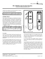
Connecting the receiver to a valve with the latching
solenoid:
1. Connect the BLACK 18 gauge stranded wire with
the 1/4 inch female terminal from the receiver to the
BLACK wire with the 1/4 inch male terminals from the
valve solenoid (see Figure 4).
2. Connect the RED 18 gauge stranded wire with the 1/4
inch female terminal from the receiver to the RED wire
with the 1/4 inch male terminals from the valve solenoid.
3. After receiver wires are connected to the valve sole-
noid wire make sure the receiver shield is located over
the receiver and then locate the receiver in an area
that will not exceed the 130° F.
IMPORTANT NOTE:
Operation of these controls is de-
pendent on which wire is attached to which terminal. If
operation of control does not correspond to operating but-
tons on transmitter, reverse wire installation at the receiv-
er or at the control.
NOTE:
Up to 6.3 VDC of power is provided at the receiver
terminal.
Figure 4. Latching Solenoid
Thermo-safety feature - receiver (T/S - RX)
When the ambient temperature at the THERMISTOR, in-
side the receiver case, reaches 130° F, the THERMIS-
TOR will automatically send 2 pulses of power to the off
terminal on the valve to shut the fireplace system off and
the RECEIVER will begin emitting a series of 2 “beeps”
every 4 seconds.
When the ambient temperature, at the RECEIVER, drops
between 120° F and 130° F, the user can reactivate the
fireplace by pushing either button on the transmitter.
When any transmitter button is pressed, the THERMIS-
TOR “resets” itself and the fireplace will begin operat-
ing again. However, the “beeping” will continue, if the
ambient temperature remains between 120° F and 130°
F. This “beeping” alerts the user that the RECEIVER
should be repositioned so the ambient temperature
drops below 120° F.
When the temperature drops below 120° F, the “beep-
ing” will cease, providing the user has “reset” the
THERMISTOR by pushing either transmitter button to
operate the fireplace. Allow sufficient time for receiver
to cool below 120° F, and then press transmitter button
to stop beeping.
GENERAL INFORMATION
Matching security codes
Each transmitter can use one of 255 unique security
codes. It may be necessary to press the LEARN button
on the remote receiver to accept the transmitter security
code upon initial use, if batteries are replaced, or if a re-
placement transmitter is purchased from your dealer or
the factory.
In order for the receiver to accept the transmitter secu-
rity code, be sure the slide button on the receiver is in
the REMOTE position; the receiver will NOT “LEARN” if
the slide switch is in the OFF position. Press the LEARN
button on the remote receiver to accept the transmitter
security code by pressing in the LEARN button on the
front of the remote receiver and then pressing any but-
ton on the transmitter. A change in the beeping pattern,
at the receiver, indicates the transmitter’s code has been
accepted into the receiver. When an existing receiver has
accepted the new transmitter, the new security code will
overwrite the old one.
The microprocessor that controls the security code match-
ing procedure is controlled by a timing function. If you are
unsuccessful in matching the security code on the first
attempt, wait 1 - 2 minutes before trying again. This delay
allows the microprocessor to reset its timer circuitry and
try up to two or three more times.
OFF
Latching
Solenoid
1/4 in. Female
Terminal
1/4 in. Female
Terminal
1/4 in. Female
Terminal
1/4 in. Female
Terminal
(Back of Receiver)
LEARN
ADJ.
f i r e - p a r t s . c o m


