


2
Power setting - RC-CON
The electronics in the remote control system have the ca-
pability of “powering” two different types of DC-powered
components. If any operational problems are noted con-
tact Hearth & Home Technologies, Inc.
The RECEIVER comes from the factory programmed to
provide pulse DC voltage (5.5 VDC to 6.3 VDC) to a latch-
ing solenoid.
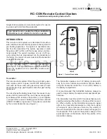
Figure 2. Remote Receiver
The remote receiver (See Figure 2) operates on four 1.5V
AA-size batteries. It is recommended that ALKALINE bat-
teries be used for longer battery life and maximum mi-
croprocessor performance.
IMPORTANT:
New or fully
charged batteries are essential to proper operation of the
remote receiver as a latching solenoid power consump-
tion is substantially higher than standard remote control
systems.
NOTE:
The remote receiver will only respond to the trans-
mitter when the 2-position slide button on the remote re-
ceiver is in the REMOTE position. The remote receiver
houses the microprocessor that responds to commands
from the transmitter to control system operation.
Functions
1. With the slide switch in the REMOTE position, the sys-
tem will only operate if the remote receiver receives
commands from the transmitter. Upon initial use or af-
ter an extended period of no use, the ON button may
have to be pressed for up to three seconds before
activating solenoid. If the system does not respond to
the transmitter on initial use, see Matching Security
Codes.
2. With the slide in the OFF position, the system is off.
3. It is suggested that the slide switch be placed in the
OFF position if you will be away from your home for an
extended period of time. Placing the slide switch in the
OFF position also functions as a safety “lock out” by
both turning the system OFF and rendering the trans-
mitter inoperative.
WARNING
: Do not connect remote receiver directly
to 110-120VAC power. This will burn out the receiver.
Follow instructions from manufacturer of gas valve
for correct wiring procedures. Improper installation of
electric components can cause damage to gas valve
and remote receiver.
INSTALLATION INSTRUCTIONS
Figure 3. Slide Switch
IMPORTANT:
The remote receiver should be positioned
where ambient temperatures do not exceed 130° F.
The remote receiver can be mounted on or near the fire-
place hearth. PROTECTION FROM EXTREME HEAT IS
VERY IMPORTANT. Like any piece of electronic equip-
ment, the remote receiver should be kept away from
temperatures exceeding 130º F inside the receiver case.
Battery life is also significantly shortened if batteries are
exposed to high temperatures.
Make sure the remote receiver switch is in the OFF posi-
tion. For best results it is recommended that 18 gauge
stranded wires should be used to make connections and
should be no longer than 20 ft.
REMOTE
ON
OFF
LEARN
ADJ.
BATTERY COVER
SLIDES ON/OFF
FREQUENC Y ADJUSTIN G
ACCESS HOLE
LEARNING
BUTTON
SLIDE
SWITCH
ON
REMOTE
OFF
REQUIRES 4-A A 1.5V
ALKALINE B ATTERIES
LEARN
ADJ.
REMOTE
OFF
Remote Receiver
f i r e - p a r t s . c o m


