


1
Printed in U.S.A. • InD • Copyright 2005
Hearth & Home Technologies Inc.
20802 Kensington Boulevard, Lakeville, MN 55044
4004-301B 10/05
RC-CON Remote Control System
- Installation and Operating Instructions -
Single-function wireless remote control system for operat-
ing valves with on/off latching solenoids.
If you cannot read or understand these installation
instructions do not attempt to install or operate.
INTRODUCTION
This remote control system was developed to provide a
safe, reliable, and user-friendly remote control system for
gas heating appliances. The system is operated manu-
ally from the transmitter. The system operates on radio
frequencies (RF) within a 20 foot range using non-direc-
tional signals. The system operates on one of 255 se-
curity codes that are programmed into the transmitter at
the factory; the remote receiver must learn the transmitter
code prior to initial use.
Review THERMO SAFETY SECTION under RECEIV-
ER section. This high temperature safety feature shuts
down the appliance when a potentially unsafe condi-
tion exists.
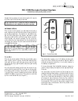
Figure 1. Remote Transmitter
This remote control system offers the user a battery-oper-
ated remote control to power an ON/OFF latching sole-
noid such as those used with gas valves used in some
decorative gas logs, gas fireplaces and other gas heating
appliances.
The circuit uses the battery power from the receiver to op-
erate a latching solenoid. The circuit has reversing polar-
ity software which reverses the positive (+) and negative
(-) output of the receiver’s battery power to drive solenoid
(ON/OFF FLAME) or open/close. The system is controlled
by the remote transmitter (see Figure 1).
The transmitter operates on a 12V battery made specifi-
cally for remote controls and electronic lighters. Before
using the transmitter install the 12 volt (A-23) battery in
the battery compartment.
It is recommended that ALKALINE batteries always be
used for longer battery life and maximum operational per-
formance.
The transmitter has ON and OFF functions that are acti-
vated by pressing either button on the face of the transmit-
ter. When a button on the transmitter is pressed, a signal
light on the transmitter illuminates to verify that a signal
is being sent. Upon initial use, there may be a delay of
three seconds before the remote receiver will respond to
the transmitter. This is part of the system’s design. If the
signal light does not illuminate, check the position of the
transmitter’s battery.
ON
OFF
SIGNAL
LIGHT
ON/OFF
BUTTONS
WALL CLIP
SLOT
12V
BATTERY
COMPARTMENT
FRONT
BACK
Transmitter
f i r e - p a r t s . c o m


