


5
Heat & Glo • PVK-80 Power Vent Instructions • 655-900 Rev. O • 12/09
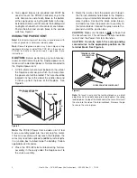
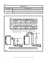
CONTROL LEVER -
REMOVE SCREW
TO ADJUST
SECURE CONTROL
LEVER WITH SCREW
AFTER ADJUSTMENT
Figure 8.
INSTALLATION INSPECTION
1. Follow safety inspection procedures recommended
by national, provincial, and/or local codes.
2. Be certain all electrical connections are properly
made and secure.
3. Visually inspect the vent system and determine that
there is no fl ue gas spillage, blockage or restriction,
leakage, corrosion or other unsafe defi ciencies.
4. Place the fi replace in operation and determine that
the burner and power vent are operating properly.
The main burner should show no signs of fl oating,
lifting, or fl ashbacks.
WARNING:
If any unsafe condition is determined
when inspecting the installation and operation of the
fi replace and Power Vent, the equipment should be
shut off. Corrections
MUST
be made before the equip-
ment is put into continuous operation.
SETTING THE EXHAUST CONTROL
The PVK-80 has an exhaust control lever which must
be set and secured during the Installation Inspection.
The lever is located behind the electrical cable connec-
tor of the cap housing and is factory set in the closed
position. See Figure 8.
The need to adjust the exhaust control will depend
upon fi replace combustion box volume, vent run con-
fi guration, and
MOST IMPORTANT
- burner fl ame
characteristics.
Leave control lever in the closed position when fi rst op-
erating the appliance during the Installation Inspection.
• If the burner fl ames are short, active, and jumping
- remove the lever screw and slightly close the ex-
haust control. Check the burner fl ames and adjust
the lever again, as necessary, until the fl ames are
stable, strong, and steady.
• If the burner fl ames are tall, lifting, fl oating, and
ghost-like the exhaust control is closed too far and
MUST
be opened.
When the burner fl ames have been optimized, secure
the exhaust control lever to the Power Vent housing
with the sheetmetal screw.
DO NOT CHANGE THIS
SETTING.
OPERATING INSTRUCTIONS
After installation of the power vent, follow the operation
instructions of the fi replace.
1. Turn the fi replace ON/OFF switch to "ON".
NOTE
: During periods of operation after turning the
fi replace "ON", there may be a slight delay before the
fi replace ignites. This is due to the time necessary for
the fan to reach operating speed and to remove any
gases from the combustion chamber.
2. After turning the switch to the "ON" position, if the
fi replace does not turn on, shut the switch to "OFF"
and inspect the power vent system for any debris
that may be obstructing the fan blade movement.
3. Turn the fi replace ON/OFF switch to "OFF" to turn
off the burner and the power vent.
MAINTENANCE
CAUTION
: Before performing any maintenance or re-
pair to the power vent assembly, make sure electrical
power is disconnected to the fi replace.
1. Vent System: Inspect all components and con-
nections annually. Replace, seal, or tighten pipe
connections if necessary.
2. Power Vent Cap: Inspect at least annually, to clear
away any debris blocking any part of the cap.
3. Motor: The fan motor bearings are sealed and no
further lubrication is necessary.


