background image

10

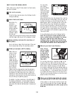
HOW TO USE THE MANUAL MODE

Note: If there is a sheet of clear plastic on the console,

peel off the plastic.

Turn on the console.

To turn on the console, press the On/Reset button

or begin pedaling. 

Select the manual mode.

Each time the

console is

turned on, the

manual mode

will be selected.

If a pace pro-

gram has been

selected, select

the manual

mode by pressing the Program button repeatedly

until the upper right corner of the display is blank. 

Begin pedaling and adjust the resistance of

the pedals.

As you exercise, adjust the resistance of the ped-

als as desired by turning the resistance knob.

Follow your progress with the display.

When the con-

sole is turned

on, the scan

mode will be

selected, as

shown by the

mode bar below

the word SCAN.

As you exercise,

the upper sec-

tion of the dis-

play will alter-

nately show the elapsed time and the distance

that you have pedaled; the lower left section of

the display will alternately show the number of

calories you have burned and the number of fat

calories you have burned; and the lower right sec-

tion will show your pedaling speed.

In addition, the pace indicator on the right side of

the display will provide a visual representation of

your pedaling pace. As you increase or decrease

your pace, the indicator will increase or decrease in

height.

To cancel the

scan mode,

press the Mode

button. The

mode bar below

the word SCAN

will disappear.

The upper sec-

tion of the dis-

play will then show only the elapsed time, and the

lower left section of the display will show only the

number of calories you have burned. Press the

Mode button again. The upper section of the dis-

play will then show only the distance pedaled,

and the lower left section of the display will show

only the number of fat calories you have burned.

To select the scan mode again, press the Mode

button repeatedly until a mode bar appears below

the word SCAN.

To reset the display, press the On/Reset button.

Note: The console can show speed and dis-

tance in either miles or kilometers. To change

the unit of measurement, hold down the

On/Reset button for about six seconds. When

the batteries are replaced, it may be necessary

to reselect the desired unit of measurement.

Measure your heart rate if desired.

Note: If there

are thin sheets

of clear plastic

on the metal

contacts of the

handgrip pulse

sensor, peel off

the plastic. 

To use the pulse sensor, hold the handle on the

console, with your right palm covering the two

right contacts and your left palm covering the two

left contacts. Avoid moving your hands. When

your pulse is detected, the heart-shaped indicator

in the display will flash each time your heart beats

and two dashes (– –) will appear. After a moment,

your heart rate will be shown. For the most accu-

rate heart rate reading, continue to hold the hand-

grips for about 15 seconds.  

When you are finished exercising, the console

will automatically turn off after a few minutes.

If the pedals are not moved and the console but-

tons are not pressed for a few minutes, the con-

sole will automatically turn off to conserve the

batteries.

6

5

4

3

2

1

Mode Bar

Pace Indicator

This corner 

should be blank

Metal

Contacts

Summary of Contents for C300e Elliptical

Page 1: ... As a manufacturer we are com mitted to providing complete customer satisfaction If you have questions or if parts are damaged or missing PLEASE CONTACT OUR CUSTOMER SERVICE DEPARTMENT DIRECTLY CALL TOLL FREE 1 888 922 4222 Mon Fri 6 a m 6 p m MST ON THE WEB www healthriderservice com Visit our website at www healthrider com new products prizes fitness tips and much more USER S MANUAL ...

Page 2: ... and properly tighten all parts regu larly Replace any worn parts immediately 6 Keep children under 12 and pets away from the elliptical exerciser at all times 7 The elliptical exerciser should not be used by persons weighing more than 250 pounds 8 Wear appropriate exercise clothes when using the elliptical exerciser Always wear athletic shoes for foot protection while exer cising 9 When mounting ...

Page 3: ...el number is HREL2005 0 The serial number can be found on a decal attached to the ellip tical exerciser see the front cover of this manual To avoid a registration fee for any service needed under warranty you must register the elliptical exerciser at www healthriderservice com registra tion Before reading further please familiarize yourself with the parts that are labeled in the drawing below FRON...

Page 4: ...y The number in parenthesis below each drawing is the key number of the part from the PART LIST on page 14 The number following the key number is the quantity needed for assembly Note Some small parts may have been pre assembled If a part is not found in the parts bag check to see if it has been pre assembled 4 M8 x 25mm Button Screw 51 4 M8 Nylon Locknut 46 4 M8 Split Washer 49 4 M10 Split Washer...

Page 5: ... and locate the wire extending from the bottom of the Console Bracket Carefully pull the upper end of the Upper Wire Harness 55 to remove any slack and tie the wire around the Upper Wire Harness as shown in the inset drawing Carefully pull the wire up through the Console Bracket until the Upper Wire Harness is extending from the top of the Console Bracket Then untie the wire and discard it Insert ...

Page 6: ...r tighten two M10 Nylon Locknuts 29 onto the studs Carefully tip the elliptical exerciser onto one side and attach the Upright 2 to the Frame 1 with two M10 x 68mm Carriage Bolts 19 and two M10 Nylon Locknuts Tighten all four M10 Nylon Locknuts See step 2 on page 5 Tighten the M10 x 25mm Button Screws 21 2 65 29 55 1 3 15 Console Cable 19 29 6 15 15 B C 15 5 While another person holds the Console ...

Page 7: ...tify the Left Pedal 13 which has an L molded into its bottom surface Attach the Left Pedal 13 to a Pedal Arm 14 with three M4 x 19mm Screws 33 Note The Left Pedal can be attached in any of three positions Attach the Right Pedal not shown to the other Pedal Arm not shown in the same way 17 17 9 38 7 9 39 46 Hexagonal Holes 50 7 Identify the Left Handlebar 9 which is marked with a sticker Insert the...

Page 8: ...STANCE To increase the resistance of the pedals turn the resis tance knob clockwise to decrease the resistance turn the resistance knob counterclockwise Important Stop turning the knob when turning becomes difficult or damage may result Pedal Pedal Disk Handlebars 10 Apply a thin film of grease to the shaft of a Bolt Set 27 and to the axle on the left Crank Arm 36 Slide a Pedal Spacer 64 and the l...

Page 9: ...rned Fat calories This mode displays the approximate number of fat calories you have burned see FAT BURNING on page 13 Pulse This mode displays your heart rate when you use the pulse sensor Speed This mode displays your pedaling speed Scan When this mode is selected the upper section of the display will show both the time mode and the distance mode and the lower left section of the display will sh...

Page 10: ... and the lower left section of the display will show only the number of calories you have burned Press the Mode button again The upper section of the dis play will then show only the distance pedaled and the lower left section of the display will show only the number of fat calories you have burned To select the scan mode again press the Mode button repeatedly until a mode bar appears below the wo...

Page 11: ...t pace indicator changes in height during the program adjust your pedaling pace so that both indicators are the same height If your pedaling pace is slower than the current target pace setting an arrow will appear next to the pace indicators to prompt you to increase your pace if your pace is faster than the target pace an arrow will prompt you to decrease your pace Important The target pace setti...

Page 12: ... the console does not display correct feedback the reed switch should be adjusted To adjust the reed switch remove the indicated Screws 62 from both Pedal Disks 8 Pull both Pedal Disks out of the Side Shields 6 7 Rotate the right Pedal Disk so that you are able to see beneath it Remove the indicated Screws 62 from the Right Side Shield 7 Remove the indicated Screws 66 from both Side Shields 6 7 Li...

Page 13: ... exercise must be aerobic Aerobic exercise is activity that requires large amounts of oxygen for prolonged periods of time This increases the demand on the heart to pump blood to the muscles and on the lungs to oxygenate the blood For aerobic exercise adjust the intensity of your exercise until your heart rate is near the highest number in your training zone WORKOUT GUIDELINES Each workout should ...

Page 14: ...et 27 2 Bolt Set 28 4 Front Pedal Arm Bushing 29 6 M10 Nylon Locknut 30 1 Hook 31 2 Front Stabilizer Endcap 32 1 Cable Clamp 33 6 M4 x 19mm Screw 34 2 M10 x 75mm Carriage Bolt 35 2 Rear Stabilizer Endcap 36 1 Left Crank Arm 37 1 Pulley 38 1 Pivot Axle 39 2 Handlebar Leg 40 2 Crank Bearing 41 1 Flywheel 42 2 Flywheel Bearing 43 1 Magnet 44 1 Flywheel Axle 45 1 M4 x 64mm Screw 46 6 M8 Nylon Locknut ...

Page 15: ... 37 21 40 40 41 42 42 43 44 46 47 47 51 56 62 15 38 61 66 57 39 55 65 17 17 50 46 50 46 39 46 59 60 53 45 66 62 66 66 24 28 20 31 24 62 35 27 27 28 28 18 18 58 66 66 66 66 62 62 62 16 60 59 53 67 63 19 54 22 62 33 33 51 49 49 49 51 68 68 52 52 64 64 67 29 29 66 EXPLODED DRAWING Model No HREL2005 0 R0805B 15 ...

Page 16: ...roduct or damage to a product caused by or attributable to freight damage abuse misuse improper or abnormal usage or repairs not provided by an ICON authorized service center products used for commercial or rental purposes or products used as store display models No other warranty beyond that specifically set forth above is authorized by ICON ICON is not responsible or liable for indirect special ...

Reviews: