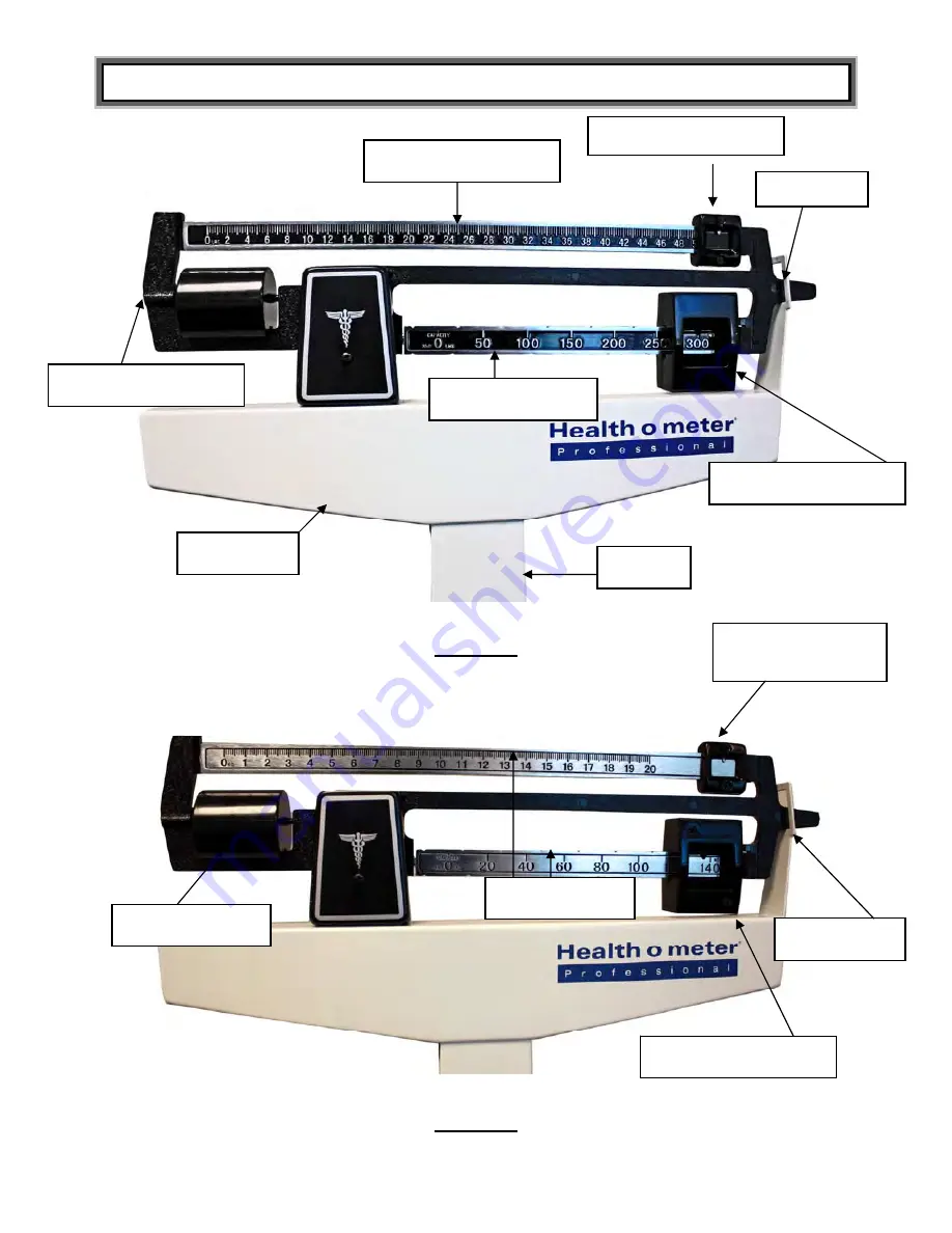
OPERATING INSTRUCTIONS (CONT)
Upper poise weight
14
Upper poise bar
Pointer
Balance ball screw
Lower poise bar
Lower poise weight
Pillar head
Pillar
Figure 11
Trig loop
Kilograms (kg)
Upper Poise
Weight
Balance ball
Figure 12
Page 1: ...Model 450KL Physician Beam Scale User Instructions PELSTAR LLC 9500 West 55 th Street McCoo IL 60525 k P N UM450KL Rev 081914 1...
Page 2: ...Assembly Instructions 450KL Scale 5 Transportation 10 Operating Instructions 13 Counterweight Instructions 16 Height Measurement Instructions 21 Troubleshooting 23 Maintenance 24 Warranty 25 Note Thi...
Page 3: ...onal service personnel To prevent patient injury the patient must be attended throughout the entire weighing event SPECIFICATIONS FOR THIS SCALE General The Model 450KL physician beam scale employs a...
Page 4: ...ing medical devices 93 42 EEC 450KL Scale Disposal This Health o meter Professional scale must be disposed of properly as steel waste Follow the national regional or local regulations which apply to y...
Page 5: ...t you will find inside the main carton as you unpack the parts for assembly To prevent scratching any components and avoid damaging the scale parts when unpacking do not use a box cutter knife scissor...
Page 6: ...scale platform at an angle resting the top of the pillar on any convenient support Using the wrench provided secure the pillar to the scale platform with the four nuts see Figures 4 5 7 Pull the stee...
Page 7: ...450KL ASSEMBLY INSTRUCTIONS CONTINUED 450KL Assembly Figure 1 Figure 2 7...
Page 8: ...450KL ASSEMBLY INSTRUCTIONS CONTINUED Tie wrap Figure 3 8 Pillar nuts Finger pull loop Studs Finger pull loop Figure 4...
Page 9: ...450KL ASSEMBLY INSTRUCTIONS CONTINUED Figure 5 Pillar nuts Finger pull loop Steel rod Lever extension Figure 6 9...
Page 10: ...he wheel bracket 2 Tip the scale forward until top front of the pillar is resting on the floor 3 Position the clamping plate inside the base and align the clamping plate wheel bracket and base assembl...
Page 11: ...TRANSPORTATION CONTINUED 11 55000 Wheel bracket Figure 7 Figure 8...
Page 12: ...TRANSPORTATION CONTINUED Clamping plate Figure 9 Mounting screws Wheel bracket Base Figure 10 12...
Page 13: ...ng equally within the trig loop opening the patient s weight can be determined 3 The patient weight can be recorded in either pounds or kilograms 4 Observe the location of the indicator arrow built in...
Page 14: ...NS CONT Upper poise weight 14 Upper poise bar Pointer Balance ball screw Lower poise bar Lower poise weight Pillar head Pillar Figure 11 Trig loop Lower poise weight Kilograms kg Upper Poise Weight Ba...
Page 15: ...s 37 5 lb 37 lb 8 oz Combined value 150 lb 37 5 lb 187 5 lb Or Combined value 150 lb 37 lb 8 oz 187 lb 8 oz Indicator Value reads 150 lb Figure 13 Value reads 17 kg 15 Figure 14 Value reads 80 kg Indi...
Page 16: ...the small poise weight to match the patient weight The poise bar will center in the trig loop Note To read a patient weight refer to Recording a Patient Weight section below 4 Read and record the weig...
Page 17: ...patient weight refer to Recording a Patient Weight section below 4 Read and record the weight Counterweight Instructions for Weighing a Patient 181 200 kg see Figures 17 23 1 When a patient weighs be...
Page 18: ...le If a patient weighs 171 kg 1 When a patient weighs 171 kg place the lower poise weight at 120 kg 2 Place the 40 kg counterweight on the 5th notch from the left between the 60 and 80 kg value 3 Adju...
Page 19: ...COUNTERWEIGHT INSTRUCTIONS CONT Counterweight Set 55070 Figure 15 3rd Notch from the left 5th Notch from the left Figure 16 19...
Page 20: ...COUNTERWEIGHT INSTRUCTIONS CONT Figure 17 5th Notch from the left 351 388 lb Assembly Figure 18 20...
Page 21: ...COUNTERWEIGHT INSTRUCTIONS CONT 389 424 lb Assembly Figure 19 401 440 lb Assembly Figure 20 451 500 lb Assembly Figure 21 21...
Page 22: ...COUNTERWEIGHT INSTRUCTIONS CONT 161 180 kg Assembly Figure 22 181 200 kg Assembly Figure 23 22...
Page 23: ...ove the patient s head 2 Position the patient against the height rod 3 Ensure that the patient s posture is upright and that the patient s head is straight and level 4 Push the headpiece down until it...
Page 24: ...46 3 Height Rod Below 8 46 3 Height Rod Extended Above Indicator 24 Inches read 41 3 8 41 3 8 Cm read 105 cm 0 2 cm 105 2 cm 8 2 Figure 9 2 Figure Cm read 176 cm 0 2 cm 176 2 cm Inches read 69 3 8 69...
Page 25: ...e weights are firmly against the shoulder of the beam Adjust the balance ball screw by turning the screw at the left end of the bar Bar does not move freely Bar sticking or adjustment needed Check if...
Page 26: ...ing device Items such as clothing or towels placed or dropped on the scale may cause it to operate incorrectly In order to prevent this do not store or leave anything on the scale 5 If your scale fail...
Page 27: ...thorized repair or alternations Further the warranty does not cover natural disasters such as fire flood hurricanes and tornadoes This warranty gives you specific legal rights and you may also have ot...