background image

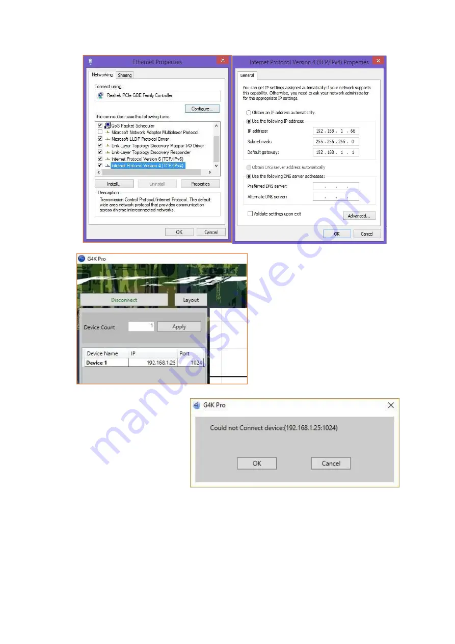
Once the control PC IP address

having been set up, press the

Connect

button to connect the Processor.

The Connect button changes to

Disconnect

button

indicating

the

connection has been set up successfully.

If a dialog window as below comes

up, the connection was failed.

Please check if control PC IP address

is correctly set up

Please check the network cable

connection between PC and G4K Pro.

Summary of Contents for HDTV-VPX104

Page 1: ...Creative Video Wall Controller HDTV VPX104 Version 2020V1 0 USER MANUAL ...

Page 2: ...d detergent for cleaning Use moisture sheet or cloth for cleaning 4 Make sure the equipment is connected to the power source with the correct voltage frequency and ampere 5 All cautions and warnings on the equipment should be noted 6 Never pour any liquid into opening this could cause fire or electrical shock 7 Never open the equipment For safety reason the equipment should only be opened by quali...

Page 3: ...ay be attached to this equipment Operation with non certified peripherals is likely to result in interference to radio and TV reception Caution Changes or modifications not expressly approved by the manufacturer could void the user s authority which is granted by the Federal Communications Commission to operate this equipment ...

Page 4: ... screens 3 2 3 Create video wall layout 3 2 3 1 Add screens onto the wall 3 2 3 2 Delete screens from the wall 3 2 3 3 Change the layout of the screens 3 3 Input 3 3 1 Manage the input 3 3 1 1 Lock aspect ratio Frame 3 3 1 2 Open input source window 3 3 1 3 Close input source window 3 3 1 4 Resize input source window 3 3 1 5 Move input source window 3 3 1 6 Change EDID 3 3 1 7 Check input resoluti...

Page 5: ...o Factory Settings Press hold for 3 seconds 3 RJ45 Ethernet Ports 4 HDMI Input Port 5 Status Lights 6 Audio Output Port 7 HDMI Output Ports 8 Daisy Chain HDMI Ports To Other Processors 9 Screw holes for Lockable HDMI cables Please take the cover screws out before use ...

Page 6: ... menu to choose the language for the software The default language is English After choosing the language click OK to continue Click I Agree to accept the License Agreement Check and uncheck the items for installation And then click Next Choose the path for installation as you wish and then click Install to start the installation process Note The installation may take several minutes to finish Cli...

Page 7: ...to change the IP address of control PC to the same IP group of this processor Open the Ethernet Properties windows on Control PC Highlight the TCP IPv4 in Networking and click the Properties button to open the TCP IPv4 Properties window Change the Obtain an IP address automatically to Use the following IP address to set up a static IP address IP address any address between 192 168 1 1 and 192 168 ...

Page 8: ...cessor The Connect button changes to Disconnect button indicating the connection has been set up successfully If a dialog window as below comes up the connection was failed Please check if control PC IP address is correctly set up Please check the network cable connection between PC and G4K Pro ...

Page 9: ...up the connection between device and control PC 2 Make sure the device has been connected and then right click the Device Name and then choose Change Device IP Address to open the Change Device IP Address dialog window 3 Please give a unique IP address for each device in the same system e g Device 1 192 168 1 25 Device 3 192 168 1 27 Device 2 192 168 1 26 Device 4 192 168 1 28 2 1 2 2 Daisy chain ...

Page 10: ... from video device directly Only the main HDMI IN port in the front panel is able to take HDMI video signal from video device directly This configuration left is an example for setting up a 4 units of processor daisy chain e g for a 4 x 4 video wall with one video source input to be displayed across the entire video wall For multi video sources input please see daisy chain examples below 3 1 2 6 C...

Page 11: ... window to choose the Slave Mode Daisy Chain mode for the 2nd unit And then 2nd to 3rd and 3rd to 4th unit For a 4x4 video wall with only one video to be displayed across the entire video wall the settings are as follows Unit 1 Main Device Unit 2 Slave get Cascade data transfer Cascade data Unit 3 Slave get Cascade data transfer Cascade data Unit 4 Slave get Cascade data transfer Cascade data 4 On...

Page 12: ...de enables the devices to have frame lock with the master device and output the signal from master device via HDMI daisy chain However it will transfer the input source from its own input to next device 4 Slave get local data transfer Cascade data Show Blue Header This mode enables the devices to have frame lock with the master device but output the signal from its own input It will however then t...

Page 13: ...sor is able to take a 4K video source either from main HDMI Input Local Data or from Daisy Chain input Cascade Data from Loop HDMI In port 2 Inputs and Daisy Chain connections using HDMI cables Note The 4th HDMI cable is needed if unit 1 would work at Slave Mode ...

Page 14: ...3 Physical connections between G4K Pro devices and video wall displays 4 Network daisy chain ...

Page 15: ... transfer Cascade data Unit 2 Main Device Unit 3 Slave get Cascade data transfer Cascade data Unit 4 Slave get Cascade data transfer Cascade data 3 Unit 1 Slave get Cascade data transfer Cascade data Unit 2 Slave get Cascade data transfer Cascade data Unit 3 Main Device Unit 4 Slave get Cascade data transfer Cascade data 4 Unit 1 Slave get Cascade data transfer Cascade data Unit 2 Slave get Cascad...

Page 16: ...ata 6 Unit 1 Main Device Unit 2 Slave get local data transfer local data Unit 3 Slave get Cascade data transfer Cascade data Unit 4 Slave get Cascade data transfer Cascade data 7 Unit 1 Main Device Unit 2 Slave get local data transfer Cascade data Unit 3 Slave get Cascade data transfer Cascade data Unit 4 Slave get Cascade data transfer Cascade data 8 And more ...

Page 17: ...the resolution of the screens Users are able to choose the resolution of screens from the drop down menu in Resolution The default output resolution is 1920 x 1080 60 Or users are able to create custom resolution if the resolution needed is not in the list By clicking in Resolution a dialog window will be shown for users to customise the resolution ...

Page 18: ...L 2 2 2 Enter the parameters of screens Dot Pitch Display area Length L Quantity of Horizontal pixel e g 1920 ...

Page 19: ...e will be applied to the video wall until Apply button has been pressed 2 2 3 Create video wall layout G4K Pro remembers the last layout used Users are able to modify the existing layout or create a new layout from scratch by deleting all the screens first 2 2 3 1 Add screens onto the wall Highlight the screens in Add to Display Wall and then press Add to Display Wall button to add the screens ont...

Page 20: ...of screen to delete the single screen 2 2 3 3 Change the layout of the screens Users are able to manipulate the screens layout to achieve a creative video wall Users are able to use drag and drop to move each individual screen to a desired position And use Angle at bottom to change the rotation of each individual screen After changing the layout and other settings users need to press Apply button ...

Page 21: ...n to open the input source window The system will automatically fit the input window onto the video wall 2 3 1 3 Close input source window Click the Close Window button to close the input source window 2 3 1 4 Resize input source window 1 Use the mouse to highlight the window and move the mouse to the border of the window The cursor will be changed to a resize cursor 2 Press and hold the left mous...

Page 22: ...e EDID needed is not in the folder users are able to customise the EDID using EDID Editor 3 4 5 After the EDID having been changed users need to disconnect and connect the input to the G4K Pro in order to apply the change 2 3 1 7 Check input resolution Users are able to check the input video resolution in the management software 2 3 1 8 Source test mode It will apply an image or video onto layout ...

Page 23: ...w Select the firmware file zip file Make sure the IP address is the same address as the unit which needs to beupdated Please update bin file first and then bit file 2 4 3 V Version of firmware of devices It shows the firmware version of all the processors which are connected to the software 2 4 4 H Home Centre the layout to the grid area 2 4 5 M Show Measurements Show the length and width of the v...

Page 24: ...rocessor Open the Editor by click on toolbar 1 Open an existing EDID file from folder of processor Edid 2 Save the file as another file name before doing anychange 3 Press Read Only Modify Button to enable the edit mode 4 Press Detailed Timings to open the EDID settings ...

Page 25: ...x required frame rate 106 and save it 7 The new EDID is ready for users to load onto processors 2 4 9 Save as Save the current video wall layout onto the control PC Note please be aware the difference between layouts here and layouts in 3 4 1 2 4 10 Load Layout Load the pre set video wall layout from control PC 2 4 11 Language Change the language of the software ...

Page 26: ...evice sends the signal out Processor INPUT statue LED light will be on if input video signal presents 4 2 2 Black screen Ensure the processor and screens are powered up Ensure the connection to screens are OK Ensure the screens on correct channel DVI or HDMI or VGA Ensure the processor is on main device mode or is daisy chained properly if works as slave device Note The header of each processor in...

Reviews: