


42
Z4A
HBM
A0697-7.0 de/en/fr
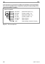
If the transducer is connected according to the following connection diagram
then when the transducer has compressive loading the output voltage at the
measuring amplifier is positive.
WH (white)
BK (black)
RD (red)
BU (blue)
GN (green)
GY (grey)
shield
Measurement signal (+) U
A
Excitation voltage (+) U
B
Sensor circuit (
−
)
Sensor circuit (+)
Excitation voltage (
−
) U
B
Measurement signal (
−
) U
A
Cable shielding, connected to housing
Six-wire connection
Fig. 6.2:
Z4A pin assignment
Summary of Contents for Z4A
Page 2: ...Deutsch Seite 3 26 English Page 27 50 Français Page 51 73 ...
Page 26: ...26 Z4A HBM A0697 7 0 de en fr ...
Page 50: ...50 Z4A HBM A0697 7 0 de en fr ...
Page 74: ...74 Z4A HBM A0697 7 0 de en fr ...
Page 75: ......