


38
Z30A
HBM
A2076-1.0 de/en
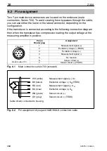
6.2 Pin assignment
Two 7-pin male device connectors are located on the enclosure (male
connectors, Series 723). To avoid creating force bypasses through the cable,
you can use either the lower or the lateral connector, depending on the
configuration.
If the transducer is connected according to the following connection diagram
then when the transducer has compressive loading the output voltage at the
measuring amplifier is positive.
Pin on
Binder plug
Assignment
1
Measurement signal (+)
2
Excitation voltage (-) (TEDS)
3
Excitation voltage (+)
4
Measurement signal (-)
5
No function
6
Sensor circuit (+)
7
Sensor circuit (-) (TEDS)
Fig. 6.1
Male connector, series 723 (screwed)
WH (white)
BK (black)
RD (red)
BU (blue)
GN (green)
GY (grey)
Measurement signal (+) U
A
Excitation voltage (+) U
B
Sensor circuit (-) (TEDS)
Sensor circuit (+)
Excitation voltage (-) U
B
(TEDS)
Measurement signal (-) U
A
Cable shield, connected to housing
Fig. 6.2
Pin assignment of plug and KAB139A-6 connection cable
6
1
5
7
2
4
3
Binder series 723
Top view
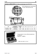
Summary of Contents for Z30A
Page 2: ......
Page 26: ...26 Z30A HBM A2076 1 0 de en...
Page 50: ...50 Z30A HBM A2076 1 0 de en...
Page 51: ...51 Z30A HBM A2076 1 0 de en...