


15
U3
HBM 11.12.2000
6
Electrical connection
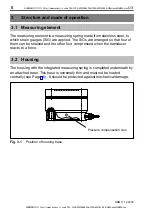
The transducers come complete with a 3m long cable with free ends. The
cable shielding is connected in accordance with the Greenline concept. This
means that the measurement system is surrounded by a Faraday cage and is
not affected by electromagnetic interference.
Connectors to CE standard are to be fitted at the free cable end of the
transducer. The shielding is here to be laid over the whole area. If a different
connection technique is used then good EMC shielding is to be provided in
the wiring loom, the shielding again being laid over the full area (see also
HBM Greenline Information, document G36.35.0).
6.1
Instructions for cabling
•
Always use shielded, low–capacity measurement cable, available from
HBM.
•
Do not lay measurement cable parallel to high–voltage power lines or
control circuits. If this is not possible (e.g. in cable ducts) protect the
measurement cable, e.g. with armoured steel tube and maintain a minimum
distance of 50 cm from the other cables. High voltage power lines and
control lines should be twisted (15 turns per metre).
•
Avoid stray fields of transformers, motors and contactors.
•
Do not earth transducer, amplifier and display device more than once. All
the devices in the measuring chain are to be connected to the same
earthed conductor.
•
The screen of the connection cable is connected to the transducer housing.
SUNSTAR传感与控制 http://www.sensor-ic.com/ TEL:0755-83376549 FAX:0755-83376182 E-MAIL:[email protected]
SUNSTAR自动化 http://www.sensor-ic.com/ TEL: 0755-83376489 FAX:0755-83376182 E-MAIL:[email protected]