


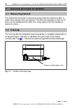


13
U3
HBM 11.12.2000
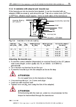
5.3.2 Installation with adapter and knuckle eye
If the transducer is to be tensile force loaded, it can be mounted with an
adapter (HBM accessory) and a knuckle eye. There is a centre hole (34
H8
mm
or 55
H8
mm, effective depth approx. 1mm) on both sides of the transducer.
H
drawing offset by
45
o
or 22.5
o
M2 (M
A
)
provided by customer
lock nut, M
B
ZGUW/1 – 5T/100kN
M1
(M
A
)
adapter
flat
B
base
flange
Fig. 5.4
Installation for tensile loading
Nominal
force (kN)
H
Max
(mm)
B
MIN
(mm)
Starting torque
M
A
(Nm)
Starting torque
M
B
(Nm)
Screws for adapter
mounting
M1
M2
0.5 – 10
108
7
5
60
M5x12
M5
20
170
18
40
300
M10x25
M10
50
180
24
40
500
M10x25
M10
100
187
24
94
1000
M10x25
M10
Attaching the knuckle eye:
•
Screw the correct adapter (dependent on nominal force!) to the U3 (please
note screw length, screw quality A2–70, at 100kN. 12.9 DIN912,
galvanized)
•
Turn the lock nut back as far as the eye
•
Screw the knuckle eye into the adapter as far as the stop
ATTENTION
Do not apply force to the transducer flange.
•
Unscrew knuckle eye 1 to 2 turns and align
•
Load eye with nominal load
•
Tighten lock nut (M
B
, lock using the flat of the adapter)
ATTENTION
When locking with the lock nut, under no circumstances let the
torque be transmitted through the transducer.
SUNSTAR传感与控制 http://www.sensor-ic.com/ TEL:0755-83376549 FAX:0755-83376182 E-MAIL:[email protected]
SUNSTAR自动化 http://www.sensor-ic.com/ TEL: 0755-83376489 FAX:0755-83376182 E-MAIL:[email protected]