


12
U3
HBM 11.12.2000
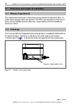
5.3
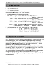
Installation for tensile loading/compressive loading
5.3.1 Installation without adapter
The transducer is screwed directly (by flange or base) on to an existing
structural element (e.g. profile, cover, plate). This type of installation enables
the transducers to measure axial forces in the tensile force and compressive
force directions. Alternating loads can also be recorded perfectly. The
transducer must be installed without axial play for this. For dynamic sustained
loading, the top and bottom threaded connectors must be prestressed by lock
nuts to above the maximum load.
drawing offset by
45
o
or 22.5
o
M
A
M
A
provided by customer
provided by customer
Flange
base
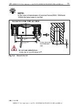
Fig. 5.3
Installation for compressive loading
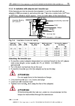
Nominal force
(kN)
Starting torque M
A
(Nm)
Thread
1)
0.5 – 10
5
4 x M5
20
40
4 x M10
50
40
8 x M10
100
94
8 x M10
2)
1)
Take note of the thread depth (see Dimensions, Page 18)
2)
12.9 DIN912 galvanized
HBM supplies knuckle eyes as mounting accessories for transducers of the
U3 type series. Knuckle eyes are suitable for use during quasi–static loading
(10Hz alternating loads). In the case of dynamic loading at a higher frequency,
you should use flexible tension bars. Knuckle eyes prevent the introduction of
torsional moments and when 2 knuckle eyes are used, stop bending moments
and transverse and angular loading being introduced in the transducers.
SUNSTAR传感与控制 http://www.sensor-ic.com/ TEL:0755-83376549 FAX:0755-83376182 E-MAIL:[email protected]
SUNSTAR自动化 http://www.sensor-ic.com/ TEL: 0755-83376489 FAX:0755-83376182 E-MAIL:[email protected]