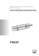
Electrical connection
PW25P
A03627_02_Y00_01
HBM: public
11
5
Electrical connection
The following can be connected for measurement signal conditioning:
S
Carrier‐frequency amplifiers
S
DC amplifiers
designed for strain gauge measurement systems.
5.1
Connection in a six‐wire configuration
Plug‐in contact 1 = measurement signal (+)
Plug‐in contact 6 = excitation voltage (-)
Plug‐in contact 5 = sense lead (-)
Plug‐in contact 7 = excitation voltage (+)
Plug‐in contact 3 = sense lead (+)
Plug‐in contact 8 = measurement signal (-)
2
3
4
5
6
7
1
8
Plug‐in contact 2 = not in use
Plug‐in contact 4 = not in use
Fig. 5.1
Connector pin assignment
With this connector pin assignment, the output voltage at the measuring
amplifier is positive when the transducer is loaded (
assignment for the cables available as accessories can be found in
.
5.2
Connection in a four‐wire configuration
When transducers in a six‐wire configuration are connected to amplifiers in a
four‐wire configuration, the sense leads of the transducer must be connected
to the corresponding excitation voltage leads: Marking (+) with (+) and marking
(-) with (-),
. This measure also reduces the cable resistance of the
Summary of Contents for PW25P Series
Page 1: ...Mounting Instructions Montageanleitung Notice de montage English Deutsch Fran ais PW25P...
Page 3: ...Mounting Instructions Montageanleitung Notice de montage English Deutsch Fran ais PW25P...
Page 19: ...Mounting Instructions Montageanleitung Notice de montage English Deutsch Fran ais PW25P...
Page 35: ...Mounting Instructions Montageanleitung Notice de montage English Deutsch Fran ais PW25P...
Page 51: ...Accessoires PW25P A03627_02_Y00_01 HBM public 17...


