background image


USE ONLY HAYWARD GENUINE REPLACEMENT PARTS 

Page 5 of 24 

Max-Flo VS Pump


IS2300VSP   Rev C 


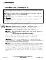
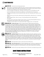
WARNING

 – Pool and spa components (seals, gaskets, etc.) have a finite life.  All components should be 

inspected frequently and replaced at least every ten years, or if found to be damaged, broken, cracked, missing, or 
not securely attached. 


WARNING


– Risk of Electric Shock

.

  All electrical wiring MUST be in conformance with applicable local 

codes, regulations, and the National Electric Code (NEC).  Hazardous voltage can shock, burn, and cause death or 
serious property damage.  To reduce the risk of electric shock, do NOT use an extension cord to connect unit to 
electric supply.  Provide a properly located electrical receptacle.    Before working on pump or motor, turn off power 
supply to the pump. 


WARNING

 – To reduce the risk of electric shock replace damaged wiring immediately.  Locate conduit to 

prevent abuse from lawn mowers, hedge trimmers and other equipment. 


WARNING


– Risk of Electric Shock

.

  In accordance with the National Electric Code (NEC), connect only to a 

branch circuit protected by a ground-fault circuit-interrupter (GFCI).  Contact a qualified electrician if you cannot 
verify that the circuit is protected by a GFCI.  The unit must be connected only to a supply circuit that is protected by 
a ground-fault circuit-interrupter (GFCI).  Such a GFCI should be provided by the installer and should be tested on a 
routine basis.  To test the GFCI, push the test circuit button.  The GFCI should interrupt power.  Push the reset button.  
Power should be restored.  If the GFCI fails to operate in this manner, the GFCI is defective.  If the GFCI interrupts 
power to the pump without the test button being pushed, a ground current is flowing, indicating the possibility of an 
electric shock.  Do not use this pump.  Disconnect the pump and have the problem corrected by a qualified service 
representative before using. 


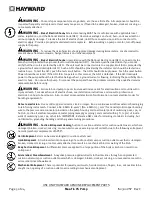
WARNING

 – Failure to bond pump to pool structure will increase risk for electrocution and could result in 

injury or death.  To reduce the risk of electric shock, see installation instructions and consult a professional 
electrician on how to bond pump.  Also, contact a licensed electrician for information on local electrical codes for 
bonding requirements. 

Notes to electrician:

  Use a solid copper conductor, size 8 or larger.  Run a continuous wire from external bonding lug 

to reinforcing rod or mesh.  Connect a No. 8 AWG (8.4 mm

2

) [No. 6 AWG (13.3 mm

2

) for Canada] solid copper bonding 

wire to the pressure wire connector provided on the pump housing and to all metal parts of swimming pool, spa, or 
hot tub, and to all electrical equipment, metal piping (except gas piping), and conduit within 5 ft. (1.5 m) of inside 
walls of swimming pool, spa, or hot tub.  IMPORTANT - Reference NEC codes for all wiring standards including, but 
not limited to, grounding, bonding and other general wiring procedures. 


WARNING


– Suction Entrapment Hazard

.  

Suction in suction outlets and/or suction outlet covers, which are 

damaged, broken, cracked, missing, or unsecured cause severe injury and/or death due to the following entrapment 
hazards (symbols complements of APSP): 

Hair Entrapment

 - Hair can become entangled in suction outlet cover. 

Limb Entrapment

 - A limb inserted into an opening of a suction outlet sump or suction outlet cover that is damaged, 

broken, cracked, missing, or not securely attached can result in a mechanical bind or swelling of the limb. 

Body Suction Entrapment

 - A differential pressure applied to a large portion of the body or limbs can result in an 

entrapment.  

Evisceration/ Disembowelment

 - A negative pressure applied directly to the intestines through an unprotected 

suction outlet sump or suction outlet cover which is damaged, broken, cracked, missing, or unsecured can result in 
evisceration/disembowelment. 

Mechanical Entrapment

 - There is potential for jewelry, swimsuits, hair decorations, fingers, toes, or knuckles to be 

caught in an opening of a suction outlet cover resulting in mechanical entrapment. 


Summary of Contents for Max-Flo VS SP2300VSP

Page 1: ...ilters heaters and pool cleaning equipment The totally enclosed permanent magnet motor combined with its advanced hydraulic design provides unparalleled energy savings Max Flo VS is designed for pools...

Page 2: ...11 5 1 Input Power Wiring 11 6 Startup Operation 11 6 1 Prior to Start Up 11 6 2 Starting Priming the Pump 11 6 3 User Interface Summary 12 6 4 Menu Outline 13 6 5 Initial startup 13 6 6 Configuration...

Page 3: ...USE ONLY HAYWARD GENUINE REPLACEMENT PARTS Page 3 of 24 Max Flo VS Pump IS2300VSP Rev C 11 Troubleshooting 20 11 1 General Problems 20 11 2 Error Codes 22 12 Warranty 22 13 Product Registration 23...

Page 4: ...Electric Code NEC USE OF NON HAYWARD REPLACEMENT PARTS VOIDS WARRANTY ATTENTION INSTALLER THIS MANUAL CONTAINS IMPORTANT INFORMATION ABOUT THE INSTALLATION OPERATION AND SAFE USE OF THIS VARIABLE SPE...

Page 5: ...NING Failure to bond pump to pool structure will increase risk for electrocution and could result in injury or death To reduce the risk of electric shock see installation instructions and consult a pr...

Page 6: ...e in off position and filter manual air relief valve must be in open position Before starting pump all system valves must be set in a position to allow system water to return back to the pool Do not c...

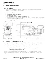
Page 7: ...mperatures below freezing without issue 2 3 Product Dimensions 3 Energy Efficiency Overview The energy consumed by a pool pump is measured in terms of Watts W or Kilowatts kW The Max Flo VS displays p...

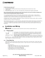
Page 8: ...erate the pump at higher speeds for the shorter periods of time needed to operate a heater water feature etc 4 Installation and Wiring WARNING This product should be installed and serviced only by a q...

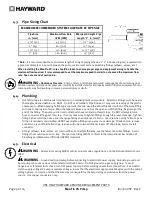
Page 9: ...layers of tape Wind the tape clockwise as you face the open end of the fitting beginning at the end of the fitting The pump suction and outlet ports have molded in thread stops Do NOT attempt to force...

Page 10: ...urrent passing between bonded metal objects which could potentially cause electrical shock if grounded or shorted Reference NEC codes for all wiring standards including but not limited to grounding bo...

Page 11: ...pressure test prior to initial use to ensure plumbing system is functioning properly then the following criteria should be maintained for this test 1 Have a professional perform this test 2 Ensure all...

Page 12: ...TION Before removing strainer cover 1 STOP PUMP before proceeding 2 CLOSE VALVES in suction and outlet pipes 3 RELEASE ALL PRESSURE from pump and piping system using filter manual air relief valve See...

Page 13: ...creen information when pressed If the DISP FUNC button is held for several seconds it will enter the controller into configuration mode The and arrow buttons are used to change parameters within confi...

Page 14: ...rotating block to emphasize the pump is in prime mode Note When Pump has finished Priming the pump will start speed V3 and display RPM Speeds can be selected at this time to temporarily run the pump h...

Page 15: ...ttings excluding the current screen settings and exit configuration mode Note The maximum allow speed for speeds V1 through V3 is 3 000 RPM The minimum allowable speed for V1 through V3 is 600 RPM The...

Page 16: ...FLASH A list of these error codes can be found in section 11 2 The cause of the internal error should be investigated and fixed before continuing to run the pump When the cause of the error has been f...

Page 17: ...sed air can cause components to explode with risk of severe injury or death to anyone nearby Use only a low pressure below 5 PSI high volume blower when air purging the pump filter or piping ATTENTION...

Page 18: ...the back of the pump 4 Remove the impeller by rotating counterclockwise 9 3 Removing the Ceramic Seat 5 Remove the spring seal assembly and seal plate from the motor by removing the four 4 3 8 x 1 bol...

Page 19: ...gasket is in place and lubricated Replace if damaged Tighten bolts alternately and evenly to 185 inch pounds Looking at the back of the pump start with the top right move diagonal to the bottom left t...

Page 20: ...bly includes parts 7 14 motor and drive 1 11 Troubleshooting 11 1 General Problems Motor Will NOT Start 1 Make sure the terminal board connections agree with the wiring diagram on the pump data plate...

Page 21: ...s Check if all system hose clamps are tight ii Check voltage to ensure that the motor is rotating at full rpm s iii Open the housing cover and check for clogging or obstruction in suction Check the im...

Page 22: ...f the error should be investigated and resolved before continuing normal operation of the pump When the issue has been resolved press the RUN STOP key to clear the error message Screen Buttons Used Co...

Page 23: ...2300VSP Rev C DATE OF INSTALLATION ____________________ INITIAL PRESSURE GAUGE READING AT 3 000 RPM CLEAN FILTER _______________________ PUMP MODEL __________________ 13 Product Registration Retain th...

Page 24: ...ll e mail communications regarding Hayward Equipment or promotions Mail to Hayward Pool Products 620 Division Street Elizabeth NJ 07207 Attn Warranty Dept Or REGISTER YOUR WARRANTY ON LINE AT WWW HAYW...

Reviews: