background image

AI 2045 - Issue B / Page 5 of 9

Images for illustration purposes only.

Product supplied may differ from that shown.

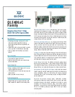
STEP B7: Cut conductors to length and strip

Cut conductor to 26mm from top of spigot. Use the groove indicator in the 

insert as a visual aid. The conductor should not extend past this cut line.

Strip conductor back past the insert shoulder which indicates the strip line 

(approx 10mm). 

The socket insert (7) may be removed from the spigot (9) to assist cable 

stripping process then re installed as shown in step B2. 

TIP: 

Use a pen to mark cores in situ then remove insert to aid conductor 

strip process.

26mm

Cut line

Strip line

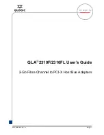
STEP B8: Fit contacts to cable conductors

Take the first contact (8), slide over the conductor and press into slot in the insert (7). The contact (8) will now be retained in the insert (7). 

Repeat for all remaining contacts

STEP B9: Check alignment of contacts

Firstly confirm all contacts (8) are concentric to the openings in the tip of the insert.

Then ensure the contacts (8) are correctly rotated so that the grub screw is in the centre of the slot.

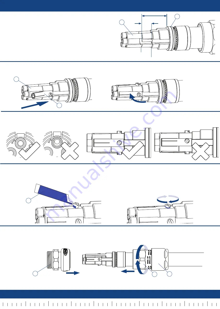
STEP B10: Apply threadlock and tighten grubscrews

Take the threadlock sachet (14) supplied with the product and tear open. Dispense a drop of threadlock onto the exposed thread of one 

contact grub screw. Tighten the grubscrew with a small screwdriver. Recommended torque is 0.75Nm. Wipe away any excess. Repeat for all 

contacts.

STEP B11: Install middlenut (11) to centrenut (6)

Screw the centrenut (6) loosely onto the middlenut (11). Do not yet tighten.

IMPORTANT: 

Ensure that the metalwork can still spin around the cable and insert assembly.

TIP:

 If the backnut (12) does not spin around cable, it may need to be unscrewed from the middlenut (11).

7

9

7

8

14

6

11

The cable has now been successfully terminated with the 501/RCG Body.

The 501/RCG Body may now either be connected to a 501/RCG Entry (see Part C) or blanked off with an energised 

end cap (see Part E).

10mm

12

10

20

30

40

5

15

25

35

45

10

20

30

40

Summary of Contents for 501/RCG

Page 1: ...t 12 Middlenut 11 Armour Spigot 9 Centrenut with Deluge Boot and O ring 6 Armour Clamp Ring 10 Socket Contact with Grub Screw 8 Socket Insert 7 Body Energised End Cap 13 Component Parts 501 RCG Entry Entry with Pin Insert 2 Crimp Pins 1 IP Washer 3 Entry Energised End Cap 4 Threadlock Sachet 14 Pin Insertion Tool 5 ...

Page 2: ...be mounted to either a plain hole in a thinwall enclosure or a threaded hole in a thick wall enclosure Fit the entry 2 to the enclosure using the IP washer 3 and locknut supplied with the product if required The product is also supplied with an optional earth tag which should also be fitted if required EQUIPMENT IP Washer if reqd AI 2045 Issue B Page 2 of 9 Images for illustration purposes only Pr...

Page 3: ...e Proceed to terminate the conductors inside the equipment as required Once installation is complete the 501 RCG Entry may be terminated in one of the following ways Fit transit cap for environmental protection Fit Entry Energised End Cap which may allow product to be energised See Part D Mate Entry with 501 RCG Body See Part C STEP A5 Fit crimped conductors into entry Using the insertion tool sup...

Page 4: ...h a spanner wrench Use a second spanner wrench to tighten half to three quarters of a turn STEP B5 Inspect Armour Braid Unscrew the middlenut 11 The armour clamp ring 10 should now be locked in place Visually inspect that the armour braid has been successfully clamped between the spigot 9 and the armour clamp ring 10 If clamping is not satisfactory repeat step B4 Cut inner sheath in line with edge...

Page 5: ...ts Firstly confirm all contacts 8 are concentric to the openings in the tip of the insert Then ensure the contacts 8 are correctly rotated so that the grub screw is in the centre of the slot STEP B10 Apply threadlock and tighten grubscrews Take the threadlock sachet 14 supplied with the product and tear open Dispense a drop of threadlock onto the exposed thread of one contact grub screw Tighten th...

Page 6: ... purposes only Product supplied may differ from that shown Part C Connecting 501 RCG Entry to Body EQUIPMENT STEP C2 Engage entry and body Ensure that the metallic outer components of the body portion can rotate freely around the cable If needed further loosen the middlenut and backnut Ensure that the keyways are aligned and hand engage the body into the entry EQUIPMENT STEP C3 Tighten Centrenut 6...

Page 7: ...NTRENUT WHILST ENGAGED RISKS DAMAGE TO THE PRODUCT EQUIPMENT 12 11 Grip here with wrench EQUIPMENT 11 6 Grip here with wrench STEP D2 Loosen Middlenut 11 Grip the centrenut 6 with a wrench ensuring it cannot turn Use a second wrench to undo the middlenut 11 and slide middlenut 11 and backnut 12 down the cable 12 Grip here with wrench EQUIPMENT STEP D4 Remove Centrenut 6 Grip the entry 2 with a wre...

Page 8: ...trenut 6 cannot turn use a second wrench to ensure the end cap 13 is wrench tight AI 2045 Issue B Page 8 of 9 Images for illustration purposes only Product supplied may differ from that shown EQUIPMENT EQUIPMENT STEP E1 Cap entry with energised end cap 4 Ensure keyways are aligned and engage end cap 4 to entry 2 by hand Hand tighten the end cap Using a wrench to ensure that the entry cannot turn u...

Page 9: ...ment Type Group II Hazardous Area Ingress Protection IP66 IP67 Operating Temp 60 C to 60 C Conductor Sizes 0 75mm2 1 5mm2 2 5mm2 4mm2 6mm2 Max Conductor Dia Entry Side Ø4 75mm Body Side Ø5 50mm INSTALLATION NOTES 1 WARNING Do not connect or disconnect when Energised 2 Product must be installed by a suitably trained and competent individual 3 Installer must check material compatability with enclosu...

Reviews: