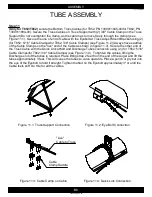
Figure 4.1: Flighting Connection
*Drive Shaft not shown for clarity
Figure 4.2: Tube Connection
*Drive Shaft not shown for clarity
Figure 5.1: Flangette and Bearing
Figure 5.2: Drive Shaft Mid
B4
ASSEMBLY
1300060439-36-00
TUBE ASSEMBLY
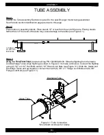
Step 4
(Only for T852/T862)
Locate the Right Truss Cable Mount Brackets (PN 1300011880-00), Left
Truss Cable Mount Brackets (PN 1300011879-00), and bolt bag PN 1300060249-00. Slide the
flighting from the Intake and Mid Tubes. Align the flighting as shown in Figure 4.1 to make
continuous. Connect the flighting with (2) 1/2" x 2-1/2" Hex Bolts and (2) 1/2" Stover Lock Nuts (see
Figure 4.1). Connect the Right Truss Cable Mount Bracket, Left Truss Cable Mount Bracket, Intake
Tube, and Mid Tube with (8) 3/8" x 1" Flange Lock Bolts and (8) 3/8" Flange Lock Nuts (see Figure
4.2). Repeat the steps to connect the Mid and Discharge Tubes as well.
Step 5
(Only for T1052)
Locate the Flangettes (PN 1300010656-00), the 1" Bore Bearings (PN
1300010670-00), Drive Shaft Mid (PN 1300011878-00), and bolt bags (PN 1300060259-00 and PN
1300060263-00). Attach (6) Flangettes and (3) 1" Bore Bearings on the Mid Tube with (6) 5/16" x 1"
Carriage Bolts and (6) 5/16" Flange Lock Nuts. Attach (4) Flangettes and (2) 1" Bearings on the
Intake Tube (on the top two Flangette Mount brackets) with (4) 5/16" x 1" Carriage Bolts and (4)
5/16" Flange Lock Nuts (see Figure 5.1). Insert the Drive Shaft Mid through the 1" Bore Bearings on
the Intake and Mid Tube (see Figure 5.2).
Intake Tube
Mid Tube
Left Truss Cable
Mount Bracket
Right Truss Cable
Mount Bracket
Bearing
Mount Bracket
Flangette
1" Bore
Bearing
Intake Tube
Drive Shaft Mid
Intake Tube
Mid Tube


