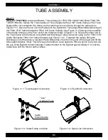
Figure 8.1: Truss Upright
*Drive Shaft not shown for clarity
Figure 8.2: Truss Support
*Drive Shaft not shown for clarity
Figure 9.1: Truss Adjust Mount Bracket
B6
ASSEMBLY
1300060439-38-00
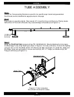
TUBE ASSEMBLY
Step 8
(Only for T852/T862)
Locate the Truss Uprights (PN 1300010163-00), Truss Support (PN
1300010174-00), and bolt bag (for T852: PN 1300060260-00/for T862: PN 1300060272-00). Mount
the Truss Uprights to the Truss Mount Bracket on the bottom of the Mid Tube and on the top of the
Discharge Tube with (for T852: (8) 3/8" x 1" Carriage Bolts and (8) 3/8" Flange Lock Nuts/for T862:
(12) 3/8" x 1" Carriage Bolts and (12) 3/8" Flange Lock Nuts (see Figure 8.1). Attach the Truss
Support to the Truss Uprights with (2) 3/8" x 1" Carriage Bolts and (2) 3/8" Flange Lock Nuts (see
Figure 8.2).
Step 9
(Only for T852/T862)
Locate the Truss Adjust Mount Brackets (PN 1300030976-00). Mount the Truss
Adjust Mount Brackets on the bottom of the Main Frame Mount Bracket on the Intake Tube with (2)
5/8" x 1-1/2" Flange Lock Bolts and (2) 5/8" Flange Lock Nuts (see Figure 9.1).
Truss Upright
Truss Mount
Bracket
Truss Support
Intake Tube
Main Frame
Mount Bracket
Truss Adjust
Mount Bracket


