MODU-FIRE® Forced Draft Gas-Fired Boiler
35
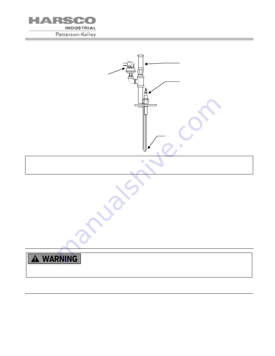
5.2.2 Ignition Assembly
NOTICE! The electrode height is not adjustable. If adjustment is necessary, only the ground rod
should be adjusted. Check for cracking of the electrode. Do NOT over tighten the electrode (finger
tight plus a quarter turn).
1.
Use a soft, clean cloth to remove accumulated contaminants from the UV detector/scanner glass envelope.
2. Before re-installing the burner, check the cleanliness of the heat exchanger and the condition of the combus-
tion chamber. If corrosion or leaks are noticed, please call for service.
3. Install the burner and blower assembly. Reconnect the green ground wire, ignition wire, high gas pressure
switch wires, the wire plug to the blower, the two air gas mixer sensing tubes, the UV scanner, and wires to
the back pressure switch. Before starting the boiler make sure to reconnect and tighten the gas union!
4. Reinstall all covers.
5. Fire Test the boiler and use a combustion analyzer to ensure that the fuel/air ratio is set correctly. If adjust-
ment is required, refer to section 3.12.3.
5.3 R
EMOVING THE
H
EAT
E
XCHANGER
Heat Exchanger is heavy and may cause injury if improperly handled.
Removal of the heat exchanger should be performed only by knowledgeable and experienced
personnel.
5.4 A
FTER
A
LL
R
EPAIRS OR
M
AINTENANCE
1.
Follow "Pre-Start Check List" (Section 3.10) and all "Safety Checks" (Section 3.11).
2. Fire the Boiler and perform combustion check.
3. Adjust gas flow if necessary. (See "Gas Pressure Adjustment", Section 3.12.3)
Spark Gap
1/8” +1/16, -0
Ignitition
Electrode
High
Exhaust
Back
Pressure
Switch
UV Detector


