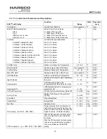
ENVI
®
Control
27
1.8.4.3
Header Mode = 1, (Header ODA & Stat)
Sensor kits required to sense header & outdoor temperatures. A list of accessory choices for different applications
is shown in section 1.0 on page 3.
In this mode, the temperature is maintained at the location of the header sensor based on a reset schedule that is
determined from an outdoor air sensor. The parameters for changing the reset schedule are in PROGRAM
PARAMETERS>CH SETTINGS. An external thermostat wired to the enable/disable circuit controls the heat
demand. Upon an enable signal from the closure between terminals TB1-1 & TB1-2, the ENVI
®
control on the
Master boiler fires and modulates the boilers to maintain header water temperature at the header setpoint which
changes based on outdoor temperature. The upper (HYST STOP BLR) and lower (HYST START BLR)
temperature differentials in conjunction with other cascade settings control the header temperature at which boilers
are added or removed.
NOTE: The outdoor air shutdown does not prevent the boiler from running in this mode.
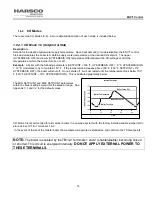
NOTE:
The cascade system is enabled by the TB1/LV terminals 1 and 2 (enable/disable) on the master boiler
becoming closed or shorted.
This circuit is energized internally.
DO NOT APPLY EXTERNAL POWER TO THESE TERMINALS.
1.8.4.4
Header Mode = 2, (Header & ODA)
Sensor kits required to sense header & outdoor temperatures. A list of accessory choices for different applications
is shown in section 1.0 on page 3.
In this mode, the temperature is maintained at the location of the header sensor based on a reset schedule that is
determined from the outdoor air sensor. The parameters for changing the reset schedule are in PROGRAM
PARAMETERS>CH SETTINGS.
The boiler is enabled when the temperature of the outdoor sensor drops below the ODA SHUTDOWN temperature
that can be changed within the CH settings.
NOTE:
The TB1/LV terminals 1 and 2 (enable/disable) operate the switching on/off of the night setback function. The
night setback setpoint is found within CH settings and when enabled, reduces the present set point by its value on
closure of the TB1 1&2 circuit.
This circuit is energized internally.
DO NOT APPLY EXTERNAL POWER TO THESE TERMINALS.
1.8.4.5
Header Mode = 3, (Header Setpoint Control)
Sensor kit required to sense header temperature. A list of accessory choices for different applications is shown in
section 1.0 on page 3.
This mode is similar to Header Mode = 0, Header & Stat, described in 1.8.3.3, except there is no external
thermostat. The heat demand is continuously maintained and controlled by the header sensor and header setpoint
relations.
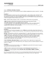
NOTE:
The TB1/LV terminals 1 and 2 (enable/disable) operate the switching on/off of the night setback function. The
night setback setpoint is found within CH settings and when enabled, reduces the present set point by its value on
closure of the TB1 1&2 circuit.
This circuit is energized internally.
DO NOT APPLY EXTERNAL POWER TO THESE TERMINALS.


