19
3.1 Packaging/Siting
The heater will usually be supplied wrapped
in heavy gauge polythene, non assembled
parts will be supplied separately.
Prior to installation, the assembly of the
heater should be completed, it is advisable
that this is undertaken in the area where the
heater is scheduled to be sited.
Caution
It is strongly advised that when positioning
the heater the lifting eyes are used, thereby
reducing the risk of inadvertent damage
being occasioned to the heater.
3.2 Flooring
The heater must be installed on a level non-
combustible surface capable of supporting
the weight of the heater and any ancillary
equipment.
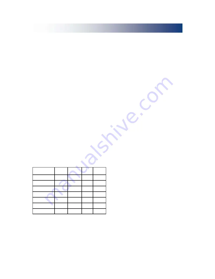
3.3 Minimum clearances
The following minimum clearances (in
millimeters) are recommended when
installing the heater.
3.4 Assembly
The following sub-assembly parts should be
assembled to allow installation to continue.
(a) Vertical Nozzled Models
For free blowing applications it will be
necessary to complete the final assembly
before continuing with the installation. The
bonnet top with nozzle spigots should be
attached to the heater and secured. The
nozzles should then be pushed home on the
spigots and positioned to provide the
desired airflow.
Ensure louvres are adjusted outwards
and ensure blades are not resonating.
The nozzles should be securely fixed in their
desired position on completion of
commissioning.
(b) Horizontal Nozzled Models
Remove packaging and secure the 90°
Duct
Outlet to the outlet on the heater using the
bolts supplied.
Secure the nozzle spigot plate to the duct
outlet using the bolts and prevailing torque
nuts provided. Fit the securing brackets to
each of the outlet nozzles, and lift the
complete heater assembly and position on
the pre-sited purpose built supports. Finish
off the assembly by fitting and securing the
outlet nozzles to the spigots by way of
previously fitted brackets.
3.5 Flue Installation
An integral flue spigot is fitted to all Cabinet
Heaters thereby allowing the flue to connect
directly to the heater.
The design of the flue must ensure that it
can be disconnected to allow for cleaning
and servicing, furthermore, all of the flue
section joint sockets must face upwards,
and the seal between the sections achieved
through mechanical joints or through the use
of approved caulking string and grout.
It is strongly advised that BS 5854 and BS
5440 parts 1 and 2 are referred to, see also
figs 9 - 19.
Where condensation is likely to be a
problem provision should be made
preferably at the design stage
(see section
2.11).
Model Size Front Rear
Lhs
Rhs
30 - 40
500
700
150
150
60 - 85
500
1,000
150
150
120 - 135
600
1,200
150
150
180
600
1,500
150
150
205
900
1,500
150
150
230 - 275
900
2,000
400
400
350 - 375
900
2,000
500
500
3.0 Installation
Summary of Contents for HT2000
Page 34: ...34 Wiring Diagram 20 45 605 60 85 ON OFF Riello Burner Integral CP4 230 50 1ph...
Page 35: ...35 Wiring Diagram 20 45 606 120 135 ON OFF Riello Burner Integral CP4 230 50 1ph...
Page 36: ...36 Wiring Diagram 20 45 607 60 275 ON OFF Riello Burner Integral CP4 415 50 3ph...
Page 37: ...37 Wiring Diagram 20 45 620 30 40 ON OFF Riello Burner Remote CP4 230 50 1ph...
Page 38: ...38 Wiring Diagram 20 45 621 60 85 ON OFF Riello Burner Remote CP4 230 50 1ph...
Page 39: ...39 Wiring Diagram 20 45 622 120 135 ON OFF Riello Burner Remote CP4 230 50 1ph...
Page 40: ...40 Wiring Diagram 20 45 623 60 275 ON OFF Riello Burner Remote CP4 415 50 3ph...
Page 41: ...41 Wiring Diagram 20 45 612 30 40 ON OFF Riello Burner No Controls 230 50 1ph...
Page 42: ...42 Wiring Diagram 20 45 613 60 85 ON OFF Riello Burner No Controls 230 50 1ph...
Page 43: ...43 Wiring Diagram 20 45 614 120 135 ON OFF Riello Burner No Controls 230 50 1ph...
Page 44: ...44 Wiring Diagram 20 45 615 60 275 ON OFF Riello Burner No Controls 415 50 3ph...
Page 45: ...45 Wiring Diagram 20 45 292 HI LOW option Riello Burner CP4 Control...
Page 51: ...51 9 0 Parts Lists...
Page 55: ...55 Notes...


