HARRISTON INDUSTRIES 4240 CLOD HOPPER Operator'S Manual Download Page 26

18

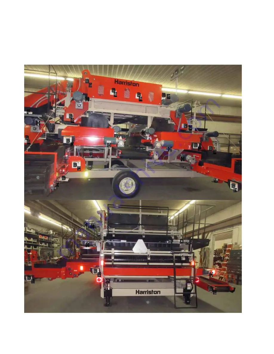
The types of safety signs and locations on the equipment are shown in the illustrations that follow. Good safety 

requires that you familiarize yourself with the various Safety Signs, the type of warning and the area, or particu-

lar function related to that area, that requires your SAFETY AWARENESS.

•  Think SAFETY! Work SAFELY!

REMEMBER - If Safety Signs have been damaged, removed, become illegible or parts replaced without safety 

signs, new signs must be applied. New safety signs are available from your authorized dealer.

B E

B E

B

E

B

E

B

E

B

B

B

B

E

E

E

E

B

E

B

B

B

E

E

E

B

E

B

E

B

E

H

H

H

H

H

F

D

H

H

H

H

H

Summary of Contents for 4240 CLOD HOPPER

Page 1: ...HARRISTON INDUSTRIES 4240 CLOD HOPPER OPERATOR S MANUAL ...

Page 2: ... implied and all other obligations or liabilities on our part of any kind or character including liabilities for alleged representations or negligence We neither assume nor authorize any other person to assume on our behalf any liability in connection with the subsequent sale of the Clod Hopper This warranty does not cover parts and accessories which are under separate guarantees from the manu fac...

Page 3: ...t by the dealer and signed by both the dealer and the customer at the time of delivery Customer s Name___________________________ Dealer s Name_ ___________________________ Address___________________________________ Address_________________________________ City State Prov Code________________________ City State Prov Code______________________ Phone Number _____ ____________________ Conveyor Model_...

Page 4: ......

Page 5: ...ering parts or requesting service or other information The serial number plate is located where indicated Please mark the number in the space provided for easy reference Clod Hopper _______________________________ Model _______________________________ Serial Number _______________________________ SERIAL NUMBER LOCATION ...

Page 6: ......

Page 7: ... Safety 9 2 12 Electrical Safety 10 2 13 Employee Sign Off Form 11 3 Safety Sign Locations 13 4 Operation 21 4 1 To the New Operator or Owner 21 4 2 Machine Components 22 4 3 General Operation Theory 25 4 4 Machine Break In 26 4 5 Pre Operation Checklist 26 4 6 Controls 27 4 7 Machine Set Up 32 4 8 Operating 34 4 9 Storage 47 4 10 Transport 48 5 Service and Maintenance 49 5 1 Service 49 5 2 Mainte...

Page 8: ......

Page 9: ...ting recommendations contained within this Operator s Manual This manual applies to the 4240 Clod Hopper manufactured by Harriston Certain options may be available to specifically tailor the Clod Hopper to your operation and may not be included in this manual Please contact the manufacturer regarding additional information about these options Use the Table of Contents and Index as a guide to find ...

Page 10: ...2 ...

Page 11: ...t symbol means ATTENTION BECOME ALERT YOUR SAFETY IS INVOLVED 3 Big Reasons DANGER Indicates an imminently hazardous situ ation that if not avoided will result in death or serious injury This signal word is to be limited to the most extreme situa tions typically for machine components that for functional purposes cannot be guarded WARNING Indicates a potentially hazardous situ ation that if not av...

Page 12: ...d understood all operating and safety instructions is not qualified to operate this machine An untrained operator exposes himself and bystanders to possible seri ous injury or death Do not modify the equipment in any way Unau thorized modification may impair the function and or safety and could affect the life of the equipment Think SAFETY Work SAFELY 2 1 GENERAL SAFETY 1 Read and understand the O...

Page 13: ...rk with this equipment Do not allow persons to operate or assemble this unit until they have read this manual and have developed a thorough understanding of the safety precautions and of how it works Review the safety instructions with all users annually 6 This equipment is dangerous to children and persons unfamiliar with its operation The opera tor should be a responsible properly trained and ph...

Page 14: ...th your other equipment 6 Train all new personnel and review instructions frequently with existing workers Be certain only a properly trained and physically able person will operate the machinery A person who has not read and understood all operating and safety instruc tions is not qualified to operate the machine An untrained operator exposes himself and bystand ers to possible serious injury or ...

Page 15: ...lear working area of debris trash or hidden ob stacles that might be hooked or snagged causing injury damage or tripping 5 Operate only in daylight or good artificial light 6 Be sure machine is properly stabilized adjusted and in good operating condition 7 Ensure that all safety shielding and safety signs are properly installed and in good condition 8 Before starting give the machine a once over f...

Page 16: ...dition before operating 9 Review safety related items annually with all per sonnel who will be operating using or maintaining the Clod Hopper 2 8 MAINTENANCE SAFETY 1 Good maintenance is your responsibility Poor maintenance is an invitation to trouble 2 Follow good shop practices Keep service area clean and dry Be sure electrical out lets and tools are properly grounded Use adequate light for the ...

Page 17: ...egard ing transporting agricultural equipment on public roadways 2 Make certain that all wheels and tires are in good repair and that tires are inflated to proper pressure Do not under inflate or overinflate 3 Make certain that all wheel lug bolts are tightened to proper torque specifications 4 Install the transport cylinder locks on the input con veyor and folding conveyor before transporting 5 A...

Page 18: ...Clod Hopper 4 Turn machine OFF shut down and lock out power supply safety lockout devices are avail able through your Harriston dealer parts de partment and wait for all moving parts to stop before servicing adjusting maintaining or re pairing any part of the electrical system 5 Disconnect power before resetting any motor 6 Replace any damaged electrical plugs cords switches and components immedia...

Page 19: ...w anyone else to operate this equipment until such information has been reviewed Annu ally review this information before the season start up Make these periodic reviews of SAFETY and OPERATION a standard practice for all of your equipment We feel that an untrained operator is unqualified to operate this machine A sign off sheet is provided for your record keeping to show that all personnel who wi...

Page 20: ...12 ...

Page 21: ...Signs the type of warning and the area or particu lar function related to that area that requires your SAFETY AWARENESS Think SAFETY Work SAFELY REMEMBER If Safety Signs have been damaged removed become illegible or parts replaced without safety signs new signs must be applied New safety signs are available from your authorized dealer A 93041 93017 93040 93042 93041 93017 93040 93042 B B H F F C D...

Page 22: ... familiarize yourself with the various Safety Signs the type of warning and the area or particu lar function related to that area that requires your SAFETY AWARENESS Think SAFETY Work SAFELY REMEMBER If Safety Signs have been damaged removed become illegible or parts replaced without safety signs new signs must be applied New safety signs are available from your authorized dealer ...

Page 23: ...h the various Safety Signs the type of warning and the area or particu lar function related to that area that requires your SAFETY AWARENESS Think SAFETY Work SAFELY REMEMBER If Safety Signs have been damaged removed become illegible or parts replaced without safety signs new signs must be applied New safety signs are available from your authorized dealer B E E 93043 93044 93052 ...

Page 24: ...ous Safety Signs the type of warning and the area or particu lar function related to that area that requires your SAFETY AWARENESS Think SAFETY Work SAFELY REMEMBER If Safety Signs have been damaged removed become illegible or parts replaced without safety signs new signs must be applied New safety signs are available from your authorized dealer H 93041 H B E H F D F ...

Page 25: ...type of warning and the area or particu lar function related to that area that requires your SAFETY AWARENESS Think SAFETY Work SAFELY REMEMBER If Safety Signs have been damaged removed become illegible or parts replaced without safety signs new signs must be applied New safety signs are available from your authorized dealer B B E E E E E B E H F E E F A B B B B B E B E B F D B E H D D F ...

Page 26: ...ing and the area or particu lar function related to that area that requires your SAFETY AWARENESS Think SAFETY Work SAFELY REMEMBER If Safety Signs have been damaged removed become illegible or parts replaced without safety signs new signs must be applied New safety signs are available from your authorized dealer B E B E B E B E B E B B B B E E E E B E B B B E E E B E B E B E H H H H H F D H H H H...

Page 27: ...he various Safety Signs the type of warning and the area or particu lar function related to that area that requires your SAFETY AWARENESS Think SAFETY Work SAFELY REMEMBER If Safety Signs have been damaged removed become illegible or parts replaced without safety signs new signs must be applied New safety signs are available from your authorized dealer H E E H ...

Page 28: ... Safety Signs the type of warning and the area or particu lar function related to that area that requires your SAFETY AWARENESS Think SAFETY Work SAFELY REMEMBER If Safety Signs have been damaged removed become illegible or parts replaced without safety signs new signs must be applied New safety signs are available from your authorized dealer B B B B B H A E E E E H H H ...

Page 29: ...ng vehicle signs reflectors and lights required by law are in proper place and are clearly visible to all traffic Be sure the tow vehicle has adequate capacity and weight to safely tow the Clod Hopper Be sure to positively hitch to the towing vehicle Use a retainer on the pin and a safety chain to assure a safe hitch hook up when transporting Adhere to local regulations regarding maximum weight wi...

Page 30: ...rform best when a single layer of potatoes moves across the rollers The 4240 divides the flow of potatoes into a large and small sizes in the sizing table in the center of the frame This fea ture increases the capacity and performance of the machine Small potatoes move forward and the large ones move back After the dirt and stones have been removed the clean potatoes can be combined Fig 1A MACHINE...

Page 31: ...23 H a M F G K L E X A N J W Q D S Q W N R Z T A P E B ...

Page 32: ...24 Fig 1B MACHINE COMPONENTS V Y M O P N L a X U a F W R Q G H J a O R Y S T E ...

Page 33: ... where they are separated into streams of large and small sizes Use the spacing on the sizing table to maintain an equal quantity of potatoes in each stream Each stream of potatoes is directed over a separator roller system to remove most of the remaining trash Cross conveyors move the clean large and small potatoes to the left side for discharge The trash stream is conveyed to move across a secon...

Page 34: ... your new Clod Hop per requires that each operator reads and follows all safety precautions and operating procedures con tained in this section Performing the following pre operation checklist is important for personal safety as well as for continued mechanical soundness and longevity of your new Harriston Clod Hopper The checklist should be performed before operating the machine and prior to each...

Page 35: ...start Then elevators cleaning table blow ers and peg conveyors start Machine is now running The starting sequence takes 13 15 seconds b Stop Switch Fig 3 This red push button latching switch turns the power to the machine OFF Depress the switch to stop machine The switch must be pulled out before the machine can be started c Forward OFF Reverse Fig 3 This 3 position rotary switch controls the Turn...

Page 36: ... Push the switch IN to stop the machine The switch must be OUT before the unit can be started Turn the switch clockwise to release it and it will pop out 3 Auxiliary Equipment Each customer must provide a means of bringing a flow of potatoes to the loading end and removing them from the discharge end plus removing the trash Normally this is done by another piece of equipment such as another convey...

Page 37: ...angle Turn clockwise to increase the angle and counter clockwise to decrease 6 Hopper Position Jack This hydraulic jack provides oil to the 2 cylin ders that set the height of the input hopper Move the control valve lever to the vertical po sition to raise the hopper and to the horizontal to lower it Set vertically to lock in position Fig 6 sizer table spacing Fig 7 discharge conveyor angle Fig 8 ...

Page 38: ... on each roll Close the relief valve on the jack base Turn the selector valve handle to the right or left to direct the flow to the upper pri mary or lower secondary roll scraper position cylinders Use the jack to position the scraper to keep the roll free of debris b Rear Rolls Large Potatoes Use the position bolts on the scraper mounts to set the scraper position The compression spring will keep...

Page 39: ... appropriately for its roller NOTE The divider has a triangular shape and can be turned as required Pull the an chor bolt out turn divider and install an chor bolt 9 Roller Position Each roller is mounted on an adjustable base al lowing it to move relative to the conveyor The roller should be positioned so the potatoes hit the roller at the 10 00 o clock position for the most effective separating ...

Page 40: ...s not need to be removed prior to the Clod Hopper being used however all workers must be reminded of its exis tence and potential tripping hazard 4 Machine Preparation a Clear the area of bystanders especially small children b Position the machine in a location with suffi cient space for the Clod Hopper and enough clearance for trucks to unload and conveyors to remove clean potatoes and trash c Po...

Page 41: ...pper This distributes the flow of material more evenly across the width of the machine for maximum capacity 7 Have a licensed electrician provide power to the machine and auxiliary equipment Be sure the power is at the required voltage and amperage and complies with ANSI NFPA 70 Protect the power cords to prevent damage 8 When the first potatoes go through the machine s check and be sure the drop ...

Page 42: ...cution Do not stand between the hopper and any vehicle backing up to the hopper Keep others away Keep the working area clean and dry Review safety instructions annually Make certain that you are in compliance with local state provincial and federal regulations regard ing transporting agricultural equipment on public roadways OPERATING SAFETY Make certain that all wheels and tires are in good repai...

Page 43: ...conds g Start the conveyors that bring potatoes to the hopper h Load potatoes into the conveying system that brings them to the hopper 5 Stopping Machine a Turn OFF the equipment that moves the po tatoes to the hopper or primary elevating conveyor b Wait until the potatoes have moved through the separating and conveying systems c Turn the Clod Hopper OFF d Turn the conveyors OFF that move potatoes...

Page 44: ...positioned on the ground for operation it will not move Do not allow the auxiliary equipment to move Normally con necting them will prevent movement 8 Conveying Speed The conveyors of the Clod Hopper and associated conveyors run at a constant speed appropriately for the separating and cleaning process Fig 18 auxiliary conveying equipment typical Clean Potatoes Trash Fig 19 conveying speed typical ...

Page 45: ...ed the potatoes move over the ta ble Extend the turnbuckles and raise the front of the frame to increase the speed of the potatoes over the table if they are relatively clean and free of debris If very dirty lower the front to allow the flow to re main longer on the Ellis table to provide a more thorough cleaning Monitor the con dition of the potatoes moving off the table Always set the cleaning t...

Page 46: ...just as required 13 Blower Optional If the machine is equipped with an optional peg belt for removing vines and stolen it will also be equipped with a blower to blow the light vines into the peg belt for removal The angle of air flow can be changed to provide the best results as required Monitor the cleanliness of the potatoes and adjust the peg belt and blower angles appropriately to give the bes...

Page 47: ...ry elevating conveyor to separate the stream of potatoes into large and small sizes The best results are obtained when the potatoes are divided into two equal flows to provide for the most efficient cleaning Use the turnbuckle on the right side of the table to adjust the table shaft spacing and keep the amount of potatoes equal in each flow Adjust shaft spacing to allow the small potatoes 1 2 volu...

Page 48: ... Small Potato Bottom View 16 Cleaning Rod Conveyor Two belted chain conveyors are located under and behind the sizing table to remove more dirt and debris from the flow of potatoes as they are moved to the rolls a Large potato b Small potato a b ...

Page 49: ...d the debris stream goes over the secondary roll Each roll can be moved relative to the end of its conveyor using the handle on one end of the frame Each handle is connected to the adjuster on the other side of the frame through a threaded rod Start with the M setting and adjust as re quired Be sure to direct the stream of potatoes to impact the roll at the 10 00 to 10 30 position for best results...

Page 50: ...trash con veyor Watch the rebound area and set the posi tion of the divider to direct the material to the ap propriately conveyor 19 Divider Each roller is designed with a divider to direct and separate the potatoes and debris after impact Start with the divider set on 2 and move as re quired to provide good separation If the divider gets dirty or covered with mud it can be turned in 120 increment...

Page 51: ...all Potato Front Each small potato roll is designed with scrapers that are positioned with hydrau lic cylinders Use the hand jack next to the platform on the left side of the frame Use the valve to select which roll and scraper will be adjusted Once the scraper is po sitioned monitor it and reposition if debris builds up on the roll b Large Potato Rear Each large potato roll is designed with sprin...

Page 52: ...eft side of the frame and the discharge a Small potato primary b Small potato collector c Small potato secondary d Small potato discharge e Large potato primary f Large potato discharge g Large potato secondary h Large potato discharge Schematic Fig 31 clean potato conveyors Typical Left Side a b c d e f g a c e ...

Page 53: ...lis table and rod conveyor one under the rod conveyor after the second elevating conveyor next to each roller divider system and a trash discharge conveyor a Under Ellis table b Under separating table c Under small potato cleaning system d Under large potato cleaning system e Along right side of frame to collect trash into one stream Fig 32 debris trash collectors Schematic Right Side Front Right ...

Page 54: ...ized by keeping the drop height between each machine and dis charge as small as possible 24 Sorters The Clod Hopper is designed with the right side dirt conveyor close to the ground to allow sorters personnel to stand next to the machine and move good potatoes from the trash to discharge con veyors Do not allow any personnel to have unre strained long hair loose clothing or jewelry when working on...

Page 55: ...ed Properly tension each conveyor belt 9 Touch up all paint nicks and scratches to prevent rusting 10 Select a storage area that is dry level and free of debris 4 9 1 PLACING IN STORAGE At the end of the season the machine should be thor oughly inspected and prepared for storage Repair or replace any worn or damaged components to prevent any unnecessary down time at the beginning of the next seaso...

Page 56: ...n the towing ve hicle when transporting TRANSPORT SAFETY 4 10 TRANSPORT Harriston Clod Hoppers are designed to be easily and conveniently transported from location to location To transport the Clod Hopper follow this procedure 1 Clear the area of bystanders especially small children 2 Disconnect and remove all auxiliary equipment from the Clod Hopper 3 Disconnect and remove the power lines Wrap an...

Page 57: ...he Clod Hopper Do not use cement blocks When completing a maintenance or service function make sure all safety shields and devic es are installed before placing unit in service 5 1 SERVICE 5 1 1 FLUIDS AND LUBRICANTS 1 Grease Use an SAE multi purpose high temperature grease with extreme pressure EP performance meeting or exceeding the NLGI 2 rating for all requirements 2 Speed Reducer Gear Box Lub...

Page 58: ... conditions may require more frequent servicing 1 All gearboxes on the machine are filled with oil and sealed from the factory Open the breather before using for the first time 2 Check the tension and alignment of conveyors a Belted Straight Offset Fig 35 gearboxes typical Elevating Flat Fig 36 belted conveyor typical ...

Page 59: ...51 b Belted chain conveyor 3 Check the tension and alignment of drive belts and roller chains a Drive belts Fig 37 POTATO CHAIN CONVEYOR Fig 38 DRIVE BELT ...

Page 60: ...hain drives Fig 39 ROLLER CHAIN DRIVES Typical Machine is shown with guards re moved or opened for illustrative purposes only Do not operate with guards removed or opened WARNING Rear Rolls Sizing Table Ellis Table ...

Page 61: ...s or Annually 1 Grease the fittings on the front swivel steering system 2 Grease discharge conveyor pivot 2 points each conveyor Pivot Pin Fig 40 steering castor base Base Fig 41 discharge conveyor pivots typical ...

Page 62: ...o roller chains Machine is shown with guards re moved or opened for illustrative purposes only Do not operate with guards removed or opened WARNING Fig 42 roller chains typical Ellis Table Drive Sizing Table Rear Rolls Product Drives ...

Page 63: ...55 4 Clean machine with a power washer Fig 43 machine ...

Page 64: ...L CLEAN G GREASE RE RE PACK LC LIGHT COAT OF OIL Hours Serviced by 50 Hours or Weekly CK Oil Level Gear Boxes CK Tension Align Conveyors CK Tension Align Drive Belts Roller Chains CK Tension Align Drive Belts Roller Chains 500 Hours or Annually G Front Swivel Steering Pivot 5 fittings G Discharge Conveyor Pivot Points LC Roller Chains Annually CL Machine ...

Page 65: ...l system and compo nents follow this procedure 1 Place all controls in the OFF or neutral position 2 Turn power OFF at the master panel and lock out before starting the inspection 3 Inspect all electrical components looking for a Damaged plugs b Frayed or loose wires c Cut or cracked insulation 4 Replace any damaged components immediately 5 Be sure all components are grounded 6 Be sure there is no...

Page 66: ... 4 Remove the fill plug Autovent breather from the gearbox 5 The Autovent plug is brass in color and will be lo cated at the highest point on the gearbox It op erates like a check valve to allow the reducer to relieve internal pressure while preventing lubricant contamination during cooling A spring presses a ball or plunger against a machined orifice un til pressure exceeds 2 psi Above 2 psi the ...

Page 67: ...ontrols in their OFF or neutral position 2 Turn the power OFF at the master panel and lock out tag out 3 Clear the area of bystanders especially small children 4 Tension The belts are tensioned correctly when there is a 1 to 2 inch 25 50 mm sag on the bottom or slack side of the conveyor during operation and the belts should not slip during operation NOTE If a belt slips during operation locate th...

Page 68: ...rning as long as it doesn t contact the sides If it contacts the sides it must be aligned Align by loosening the shaft bearing assembly on the tight side or tightening the bear ing assembly on the loose side Move the bearing assemblies on either the drive or driven shafts to align the conveyor but always maintain the proper tension Fig 46 conveyor belt alignment typical Elevating Conveyor Flat Con...

Page 69: ...ect the old belt and connect the ends of the new one together f Move the shaft into position to set the tension of the belt and secure the bearing assemblies g Check the tension and alignment of the belt frequently during the first 10 hours of opera tion and set as required Then go to the regu lar maintenance schedule Normally a belt will seat itself during the first 10 hours of operation and then...

Page 70: ...ition b Open belt by removing pin at each belt c Attach the replacement belt to the end of the old belt d Slowly pull the old belt out of the machine and thread the new one into position e Disconnect the old belt and connect the ends of the new one together f Move the shaft s into position to set the tension of the belt and secure the bearing assemblies g Check the tension and alignment of the bel...

Page 71: ... adjusting chain tension and sprocket alignment 5 2 4 1 SPRING LOADED IDLER 1 Open or remove guard 2 Loosen jam nut on the adjustment bolt 3 Push in the adjustment bolt to check for prop er compression Approximately 10 ft lbs 1 4 kg m of force should be required to compress the spring and put adequate tension on the chain 4 Rotate the adjustment bolt to adjust spring compression 5 Tighten jam nut ...

Page 72: ...sh the stationary idler toward the chain until all slack is removed from the chain 4 Tighten the bolt and nut to secure the station ary idler 5 Install and secure guard IMPORTANT If idler has run out of adjustment short en or replace chain Secondary Elevator Collector Conveyor Fig 50 stationary idler typical ...

Page 73: ...ems must be kept in alignment to insure proper performance and durability Observe the condition of the sides of the roller chain Adjust the sprocket alignment if one side of the roller chain has more wear than the other Sight along the sprockets to see which one is not aligned Loosen and move sprocket Secure sprocket ...

Page 74: ...n 4 If the belts slip during operation adjust the belt tension by following this procedure a Set the tension on the drive belts by moving the blower frame b Loosen blower position jam nut and move frame c Tighten blower frame position bolt and jam nut d Use the motor mounting bolts to move the motor for setting the belt tension if the blower frame angle can t be changed e Tighten motor mount ancho...

Page 75: ... electrical service Master switch defective Replace master switch Start switch defective Replace start switch One motor doesn t run Panel relay tripped defective Reset replace relay Motor wiring damaged defective Repair replace motor wiring Motor defective Replace motor Trash in produce conveyor produce in trash conveyor Feeding too much Slow down material entering input conveyor Uneven feeding Ev...

Page 76: ...68 ...

Page 77: ...69 SPECIFICATIONS SUBJECT TO CHANGE WITHOUT NOTICE 7 SPECIFICATIONS 7 1 MECHANICAL ...

Page 78: ...not grease or oil bolts or capscrews unless otherwise specified in this manual When using locking elements increase torque values by 5 Torque value for bolts and capscrews are identified by their head markings 8 8 N m lb ft Bolt Torque 10 9 N m lb ft 5 3 6 10 25 50 90 140 225 435 750 1495 2600 4 2 2 4 7 18 37 66 103 166 321 553 1103 1917 1 8 4 5 9 15 35 70 125 200 310 610 1050 575 3675 1 3 3 3 7 1...

Page 79: ...LECTRICAL SCHEMATIC Line phasing line voltage control voltage and accessory options can vary substantially for each machine Please contact factory at 1 800 437 8205 for your machine s specific electrical layout ...

Page 80: ...72 ...

Page 81: ...E S Safety 3 Electrical Safety 10 Employee Sign Off Form 11 Equipment Safety Guidelines 5 General Safety 4 Installation Safety 7 Lock Out Tag Out Safety 9 Maintenance Safety 8 Operating Safety 8 Preparation 7 Safety Signs 6 Safety Training 6 Storage Safety 9 Transport Safety 9 Safety Sign Locations 13 Service and Maintenance 49 Maintenance 57 Service 49 Specifications 69 Bolt Torque 70 Electrical ...

Page 82: ......

Page 83: ......

Page 84: ... INDUSTRIES 500 ORDWAY BOX 378 MINTO ND 58261 PHONE 701 248 3286 TOLL FREE 800 437 8205 FAX 701 248 3070 www harriston mayo com harriston invisimax com PRINTED IN USA ISSUE DATE FEBRUARY 2017 PART NUMBER XXXXXX ...

Reviews: