MM-015371-001, Rev. C
54
11 HEADSET/PORTABLE RADIO CONNECTIONS
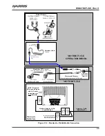
Several different-type headsets are available for use with a motorcycle-mounted M5300/M7300 mobile
radio. These headsets have helmet-mounted noise-canceling microphones, and either single or dual-
speakers. The headsets can be attached to helmets.
In addition, several different-type helmet headset interface cables are available. These cables include
those with either pushbutton or rocker-type PTT switches, both with and without CG disable switches.
Also, belt-box cable assemblies are available. A belt box allows connection of either a headset or a
portable radio to the mobile radio.
Respective option numbers are listed in Table 4-6 on page 27.
Headset speakers have a nominal impedance of 24 ohms. Using a headset with a
different speaker impedance value will result in non-optimum sound performance from
the speaker(s). The SM-KA-23 dual-speaker helmet kit has its two speakers wired in
parallel. They must be re-wired in series to perform properly.
Headset Helmet Kit Interface Cables SM-MCH-71GT and SM-MCK-71GT each have
a pushbutton switch that only supports the PTT function. However, Headset Helmet
Kit Interface Cables SM-MCH-72GT, SM-MCK-72GT, and SM-MCH-73GT each
have a three-position rocker switch that supports both the PTT and CG decode disable
functions.
11.1 CONNECTING A HEADSET TO THE RADIO (WITHOUT BELT BOX)
To connect a headset to the M5300/M7300 mobile radio (without using a belt box), follow this procedure:
1.
Open the motorcycle radio case.
2.
As illustrated in Figure 11-1 on page 55, connect the male 44-pin D-subminiature (DB-44) connector
of Headset Adapter Cable CA-012349-002 to the female DB-44 connector on the rear of the radio.
Using a small flat-blade screwdirver, tighten the two (2) jackscrews securely.
3.
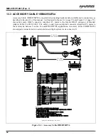
Mate the male DB-25 connector of Accessory Cable 19B802554P24 to the female DB-25 connector
of the Headset Adapter Cable. Tighten the two (2) jackscrews securely.
4.
Route the Accessory Cable’s round 8-pin waterproof connector through the square hole in the bottom
floor of the motorcycle radio case. This cable’s connector must be located near the motorcycle
operator’s/rider’s hip position, typically near the front of the saddle (i.e., motorcycle’s seat). The
connector should remain at least partially exposed so the operator/rider can easily connect to and
disconnect from it as necessary. Tie and stow the cable securely under the saddle.
5.
Inside the case, coil-up these two cables and tie and stow them securely. The female DB-25 end of the
Accessory Cable is not normally used in M5300/M7300 mobile radio motorcycle applications.
6.
Install the headset into the helmet per instructions provided with the headset.
7.
Install the PTT switch of the Headset Helmet Kit Interface Cable (option number SM-MCH-71GT,
etc.) by first mounting the PTT switch to the motorcycle’s handlebar. The PTT switch may or may
not also have a CG disable switch. Typically, the PTT switch is mounted to the left handlebar. Insure
the switch and its cable installation does not obstruct movement of the handlebar or other motorcycle
controls in any way.

