MM-015371-001, Rev. C
16
Conventional FM repeater-based and FM talk-around voice communications in 700 and 800 MHz
bands in accordance with the TIA/EIA-603 conventional land-mobile radio standard.
700 MHz operating bands of the dual-band M7300 mobile radio include the repeater output bands
(mobile receive) of 764 to 767 MHz, 769 to 775 MHz and 773 to 776 MHz, and the repeater input bands
(mobile transmit) of 794 to 797 MHz, 799 to 805 MHz and 803 to 806 MHz. The radio also provides
talk-around operation in the 764 to 767 MHz, 769 to 775 MHz and 773 to 776 MHz bands. In high-power
transmit mode on a 700 MHz RF channel, the radio’s rated transmit output power is 19 watts.
800 MHz operating bands of the dual-band M7300 mobile radio include 806 to 824 MHz repeater input
band (mobile transmit) and the 851 to 869 MHz band used for repeater output and talk-around
communications. In high-power transmit mode on an 800 MHz RF channel, the radio’s rated transmit
output power is 35 watts. However, motorcycle applications are limited to 20 watts.
The dual-band M7300 mobile radio can operate on both 700 and 800 MHz bands.
However, as of the publication of this manual, motorcycle applications are limited
to the 800 MHz band only.
3.1.4
General
Information
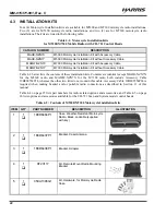
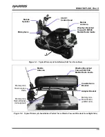
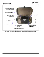
In motorcycle applications, the radio is mounted in a weather-resistant case. This case is secured to the
motorcycle’s frame behind the seat of the motorcycle. The radio’s control head is located near the
motorcycle operator position. The radio is shown in the case in Figure 5-3 on page 30.
Control heads used with the M5300 and M7300 mobile radios include the CH-721 Scan and the CH-721
System model control heads. See Figure 8-1 through Figure 8-3 (pages 40 through 41). Both heads
feature a large 3-line graphical vacuum-florescent display, front panel controls and buttons for user
control of the mobile radio, an internal high-power audio amplifier to drive an externally-connected
speaker, and a front panel microphone connector. The CH-721 System control head also has a 12-button
numeric keypad that provides Dual-Tone Multi-Frequency (DTMF) functionality and easier operator
system/group selection control at the control head’s front panel.
The radio is remotely controlled by a control head via a Controller Area Network (CAN) link between the
radio and control head. A 3-wire CAN cable provides the CAN link interconnection between the two
units. The CAN link carries digitized microphone and speaker audio, controlling data such as button
presses and radio messages, and user data such as that for a mobile data terminal connected to the serial
port of the radio or control head. For proper operation, the CAN link must be terminated appropriately on
each end.
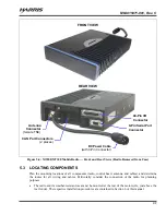
As shown in Figure 8-3 on page 41, the CH-721 Scan and System model control heads have several
connectors located on the head’s rear panel. These connectors include a DC power connector, two (2)
CAN port connectors used for CAN link interconnections, an external speaker connector, a 9-pin serial
port connector for connecting optional equipment such as a mobile data terminal, and a 25-pin accessory
connector. Both CH-721 models can interface to an optional Federal Signal Electronic siren/light control
system for broadcasting via a public address (PA) speaker.
The radio must be powered by an ex13.6-volt (nominal) DC power source. In motorcycle
applications, the motorcycle’s electrical system is utilized as the source of DC power. The control head
connected to the radio is also powered by the same DC power source, but separately fused. When the
control head is powered-up by the operator, it “wakes up” the radio by transmitting data to the radio via
the CAN link.
The radio provides half-duplex voice and data communications. Voice communications are accomplished
via a “push-to-talk” (PTT) type microphone and a speaker connected to the control head.


