background image

AES-3981 Installation and Operation Manual

27

Chapter 3: Operation

Preliminary—Contents are proprietary and confidential. Do not photocopy or distribute.

LEDs and Module Indicators

General Information

The AES-3981 has four standard module indicators:

Major alarm

Minor  alarm

Power

Module status

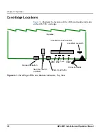
These indicators are located on the card edge of the front module, 
directly in front of the VFD. (See 

Figure 3-1

.)

The AES-3981 also generates alarm signals to alert users of failures or 
impending failures within the module. These alarm signals are found in 
the following locations:

As red or yellow LEDs on the 3901AIC Alarm Interconnect 
Module or the 3901RES-E Resource Module (visible via light 
pipes through the frame’s front panel)

As part of a list of activated alarms found in the 

Setup

 menu

In external systems connected to the alarm contact closures at 
the back of the NEO frames

On a PC screen where CCS Pilot™ CCS Navigator™, or 
another GUI-based software control application

Summary of Contents for AES-3981

Page 1: ...Edition D AES 3981 MAN AES 3981 Digital Audio Distribution Amplifiers Installation and Operation Manual...

Page 2: ......

Page 3: ...Preliminary Contents are proprietary and confidential Do not photocopy or distribute AES 3981 Digital Audio Distribution Amplifiers Installation and Operation Manual Edition D August 2006...

Page 4: ...atinum Portal PROM Slide RouterMAPPER RouterWORKS Signal Quality Manager SpyderWeb SuiteView TitleMotion UNIFRAME Velocity VelocityHD VideoCarte Videotek and X75 are trademarks of Harris Corporation w...

Page 5: ...ning Documents ix Unpacking the Module ix Safety Standards and Compliances x Restriction on Hazardous Substances RoHS Directive x Waste from Electrical and Electronic Equipment WEEE Directive xi Safet...

Page 6: ...Rebooting the Module 17 Chapter 3 Operation Overview 19 Operation Notes 20 Navigating the Operator and All Lists 21 Operator and All List Parameters 22 Setup Parameters 24 Alarms 25 Alarm Synchronizat...

Page 7: ...digital audio distribution amplifiers Audience This manual is written for technicians and operators responsible for the installation setup maintenance and operation of the AES 3981 digital audio distr...

Page 8: ...ction name Italics Indicates email addresses names of books and publications and first instances of new terms and specialized words that need emphasis CAPS Indicates a specific key on the keyboard suc...

Page 9: ...ese steps 1 Check the equipment for any visible damage that may have occurred during transit 2 Make sure that you have received all items listed on the packing list 3 Remove the anti static shipping p...

Page 10: ...tances found in electrical and electronic equipment The intent of this legislation is to reduce the amount of hazardous chemicals that may leach out of landfill sites or otherwise contaminate the envi...

Page 11: ...cers or users will be required to recycle electrical and electronic equipment at end of its useful life and may not dispose of the equipment in landfills or by using other unapproved methods Some EU m...

Page 12: ...y Terms and Symbols Used in Manual WARNING Statements identifying conditions or practices that can result in personal injury or loss of life High voltage is present Uninsulated dangerous voltage withi...

Page 13: ...al for information about NEO frames The frame manual includes information about these items General information about module unpacking installation removal navigation configuration and setup Card edge...

Page 14: ...ing hardware control panels and or a graphical user interface The 1RU NEO control panel is uncluttered and simple to use It has as large a display as is practical and a suitable number of buttons and...

Page 15: ...ese are the main features of the AES 3981 AES frame rates up to 96kHz Balanced or coaxial interface Automatic or manual EQ Reclock and non reclock modes Error detection and reporting Frame rate detect...

Page 16: ...ull local and remote control capabilities in a routing solution It is especially useful where professional end users require a small flexible high quality on air quality routing matrix with the abilit...

Page 17: ...wappable The back connector module is installed from the rear of the frame The front module accepts a single input signal from the back panel then equalizes and conditions the signal before driving th...

Page 18: ...ing the rear The AES 3981 supports either a coaxial interface or a balanced interface back module The balanced back module features 110 output impedance with a jumper selectable looping or 110 termina...

Page 19: ...1 Installation and Operation Manual 7 Chapter 1 Introduction Preliminary Contents are proprietary and confidential Do not photocopy or distribute Block Diagram Figure 1 4 Functional Block Diagram of A...

Page 20: ...8 AES 3981 Installation and Operation Manual Preliminary Contents are proprietary and confidential Do not photocopy or distribute Chapter 1 Introduction...

Page 21: ...Edition A B C or D you will need to download an updated version from the Web site www broadcast harris com leitch to access this information In this chapter you can find information on the following t...

Page 22: ...s See the NEO FR 3901 FR 3903 and FR 3923 Mounting Frames Installation and Operation Manual for details about removing NEO modules Upgrading AES 3981 Firmware Firmware upgrading is a routine procedure...

Page 23: ...s in the Select the device directory to transfer to field 4 Click Add and in the Add Upgrade Files box browse and select the boot folder in the module s upgrade click OK The Add Upgrade Files box appe...

Page 24: ...close the Configuration box The module name appears at the card edge Upgrading the Firmware Drag and Drop Method Follow these steps to upgrade the firmware using the drag and drop method 1 Download t...

Page 25: ...e click the device icon The Configuration window opens On the Software Upgrade tab the slotx boot where x is the slot number directory appears in the Select the device directory to transfer to field 7...

Page 26: ...he device directory to transfer to field 2 Click Add and in the Add Upgrade Files box browse and select the fl0 folder in the module s upgrade package 3 Click OK 4 Select the files shown in the Add Up...

Page 27: ...as described in the following pages When you are performing this procedure check the appropriate README file to confirm which files are needed Use care to ensure that you upload the correct files to t...

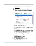
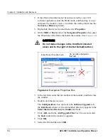
Page 28: ...ter the IP address of the frame that holds the module See Figure 2 2 Figure 2 2 Navigation Properties Box 5 In the last field enter the slot number of the module and then close the window 6 Double cli...

Page 29: ...der in the module s upgrade package 5 Click OK 6 Select the files shown in the Add Upgrade Files box and then click OK 7 Select and delete unwanted files for example vxWorks lzs in the Add upgrade fil...

Page 30: ...18 AES 3981 Installation and Operation Manual Preliminary Contents are proprietary and confidential Do not photocopy or distribute Chapter 2 Installation and Removal...

Page 31: ...on and Operation Manual If your current NEO frame manual is Edition A B C or D you will need to download an updated version from our Web site www broadcast harris com leitch to access this information...

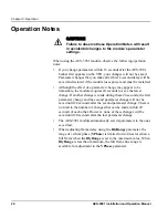
Page 32: ...is made during these 20 seconds the first parameter change and the second parameter change will not be saved until 20 seconds after the second parameter change There is no limit to the number of chan...

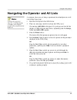
Page 33: ...e name of the first parameter option in the list will appear 4 Push the Enter button again to access the options for the parameter displayed on the VFD screen OR Press the Nav Nav switch down repeated...

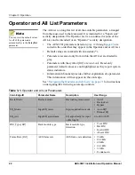
Page 34: ...only Read only parameter default values are not highlighted as they report system status indicators Information in brackets provides further explanation of a parameter This information will not appear...

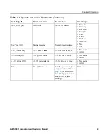
Page 35: ...nal presence detect No Yes 5V_Alarm RO 5V power alarm 5 volts out of range No alarm Alarm 5V Alarm RO 5V power alarm 5 volts out of range No alarm Alarm 3 3V Alrm RO 3 3V power alarm 3 3 volts out of...

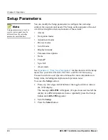
Page 36: ...About mode See Appendix A Tree View Navigation for the structure of the Setup menu See your NEO FR 3901 FR 3903 and FR 3923 Mounting Frames Installation and Operation Manual for more information on Se...

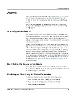
Page 37: ...set for local control the alarm settings will appear the same at both the card edge and via CCS but the settings can only be changed using the card edge controls If the module is set for remote contro...

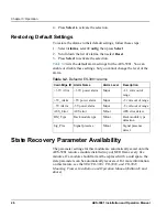
Page 38: ...bility The parameter settings for this module are automatically saved onto the AES 3981 resource module installed in your NEO frame every five minutes If a module should fail and be replaced with a co...

Page 39: ...FD See Figure 3 1 The AES 3981 also generates alarm signals to alert users of failures or impending failures within the module These alarm signals are found in the following locations As red or yellow...

Page 40: ...s the locations of the LEDs and module indicators on the AES 3981 card edge Figure 3 1 Card Edge LEDs and Module Indicators Top View Local Remote switch Top view Nav Nav switch up down Extractor handl...

Page 41: ...r Meaning Major Alarm Red One or more of the following problems in the AES 3981 module has occurred 3 3 volts out of range 5 volts out of range 5 volts out of range Minor Alarm Yellow One or more of t...

Page 42: ...30 AES 3981 Installation and Operation Manual Preliminary Contents are proprietary and confidential Do not photocopy or distribute Chapter 3 Operation...

Page 43: ...ut Specifications on page 32 AES 3981 Digital Output Specifications on page 33 Performance Specifications on page 34 Indications on page 34 Power Consumption Specifications on page 35 Temperature Spec...

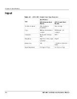
Page 44: ...tal Input Specifications Item Specification With Balanced Back Module With Coaxial Back Module Number of inputs One looping or terminated One looping Type Balanced transformer coupled Differential AC...

Page 45: ...put Specifications Item Specification With Balanced Back Module With Coaxial Back Module Number of outputs 8 8 Type Balanced transformer coupled Unbalanced Connector Removable terminal strip BNC Imped...

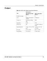
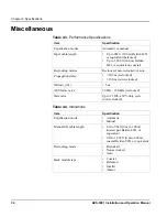
Page 46: ...1 or equivalent coaxial Reclocking modes Reclocked non reclocked or auto Propagation delay 600 ns reclocked 100 ns non reclocked Intrinsic jitter 5 ns AES frame rates 30 kHz 100 kHz reclocked Data rat...

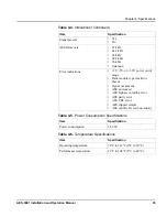
Page 47: ...t of range Back module type invalid or absent Signal not present AES not locked AES biphase encoding error AES parity error AES CRC error AES slipped sample AES validity bit set non audio Table 4 5 Po...

Page 48: ...36 AES 3981 Installation and Operation Manual Preliminary Contents are proprietary and confidential Do not photocopy or distribute Chapter 4 Specifications...

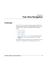
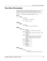
Page 49: ...s Unlike the other navigation modes the Tree View is a multilevel list of parameters arranged in the following main groups Input on page 39 Output on page 39 Status on page 39 Setup on page 39 See Set...

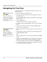
Page 50: ...the Select button The Level Two list will appear 6 Repeat steps 4 and 5 to view more items in Levels Two Three and Four 7 If the parameter is numeric slide the bar to the desired parameter using the...

Page 51: ...structions on navigating the Tree View Input Other EQ_Mode Options Auto Manual EQ_Adj Range 0 600m Output Other Reclk Mode Options Auto Reclocked Bypass Status Other BM_Type RO Options Coaxial Balance...

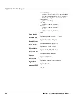
Page 52: ...ror AES Not Locked Sig_Pres RO Options Yes No 5V Alrm Options Enabled Disabled 5V Alrm Options Enabled Disabled 3 3V Alrm Options Enabled Disabled Reset Nav Mode Options Oper List All List Tree View S...

Page 53: ...a failed upgrade 15 D Description product 2 Discovery method of upgrading 11 12 Documents obtaining ix Drag and drop method of upgrading 12 14 F Fail safe procedure 15 Features 3 Firmware upgrading 10...

Page 54: ...enabling alarms 25 restoring defaults 26 synchronization 25 LEDs 27 29 module indicators 27 29 navigating the All list 21 navigating the Operator list 21 operation notes 20 parameters All list 22 23 O...

Page 55: ...43 Index temperature specifications 35 T Temperature specifications 35 Tree view navigation 38 parameters 39 40 U Unpacking modules ix Upgrading firmware 10 17 discovery method 11 12 drag and drop me...

Page 56: ...44 AES 3981 Installation and Operation Manual Index...

Reviews: