background image

9

AVR

Configure the AVR for Your Speakers: AVR 1510/AVR 151

Note: The on-screen menus shown in this guide may differ slightly from your AVR’s actual 

menu screens.

Before you use your AVR you need to configure it to work with your speakers and to 

compensate for the acoustic characteristics of your room. Before beginning, place your 

loudspeakers as explained in the 

Place Your Speakers

 section, on page 2, and connect 

them to the AVR as explained in the Connect Your Speakers section, on page 3. 

1.  Turn on your TV and select the TV input where you connected the AVR in Connect Your 

TV, on page 3.

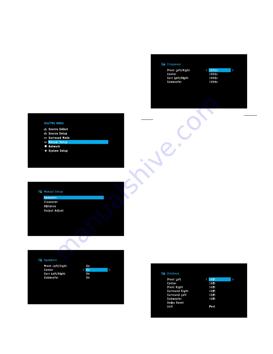
2.  Press the remote control’s OSD/Menu button. The AVR’s on-screen display (OSD) setup 

menu will appear on the TV. (Note: If you have used a composite video connection to 

your TV, the OSD menus will not appear on your TV. Follow the steps below using the 

AVR’s front-panel display.)

M A S T E R   M E N U

S o u r c e   S e l e c t
S o u r c e   S e t u p
S u r r o u n d   M o d e
M a n u a l   S e t u p
N e t w o r k
S y s t e m   S e t u p

3.  Use the remote’s arrow and OK buttons to select “Manual Setup.”

M a n u a l   S e t u p

S p e a k e r s
C r o s s o v e r
D i s t a n c e
O u t p u t   A d j u s t

4.  Select “Speakers.”

S p e a k e r s

F r o n t   L e f t / R i g h t
C e n t e r
S u r r   L e f t / R i g h t
S u b w o o f e r

O n
O n
O n
O n

5.  Use the Up/Down buttons to select a speaker group and use the Left/Right buttons to 

select “On” when the speakers are present in the system, or”Off” for positions where 

no speakers are installed. The Front Left & Right setting is always On and may not be 

disabled. (Note: The settings in this menu affect the remainder of the speaker setup 

process and the availability of various surround modes.) 

6.  Press  the  Back/Exit  button  to  return  to  the  Manual  Setup  screen,  then  select 

“Crossover.”

C r o s s o v e r

F r o n t   L e f t / R i g h t
C e n t e r
S u r r   L e f t / R i g h t
S u b w o o f e r

1 0 0 H z
1 0 0 H z
1 0 0 H z
1 0 0 H z

Consult the technical specifications for all of your speakers and locate their frequency 

response, usually given as a range, e.g., 100Hz – 20kHz (±3dB). Write down the lowest 

frequency that each of your speakers is capable of playing (100Hz in the above example). 

7.  Use the Left/Right buttons to set each speaker group’s Crossover Frequency to the 

frequency that most closely matches the frequency you noted above in the speaker’s 

specifications. If the speaker’s crossover frequency is lower than 40Hz, select the first 

option, “Large.” (This setting doesn’t refer to the speaker’s physical size but to its 

frequency response, which is also called “full range.”)

•  We recommend that you set the Subwoofer Crossover to the same frequency you use 

for the Front Left/Right speaker setting. 

Your AVR will divide the source signal at the crossover frequency; all information above 

that crossover point will be played through your system’s speakers, and all information 

below the crossover point will be played through the subwoofer. This way, each 

loudspeaker in your system will perform at its best, delivering a more powerful and 

enjoyable sound experience.

•  If you set the Front Left/Right speakers to “Large”, select one of the three following 

settings for the subwoofer:

L/R+LFE: This setting sends all low-frequency information to the subwoofer, including 

a) low-frequency information that is also played through the front left and right 

speakers and b) the special LFE (low-frequency effects) channel information that is 

present on some DVDs, Blu-ray discs and other digital programming.

LFE: This setting plays low-frequency information contained in the full-range program 

channels through the front left and right speakers, and directs only the LFE-channel 

information to the subwoofer.

OFF: Select this setting when no subwoofer is in use. All low-frequency information will 

be sent to the front left and right speakers.

8.  When you’re finished, press the Back/Exit button to return to the Manual Setup screen, 

then select “Distance.”

D i s t a n c e

F r o n t   L e f t
C e n t e r
F r o n t   R i g h t
S u r r o u n d   R i g h t
S u r r o u n d   L e f t
S u b w o o f e r
D e l a y   R e s e t
U n i t

1 0 F t
1 0 F t
1 0 F t
1 0 F t
1 0 F t
1 0 F t

F e e t

Connections

Summary of Contents for Harman/kardon AVR 1710

Page 1: ...Audio Video Receiver AVR 1710 AVR 171 230 AVR 171 230C AVR 1610 AVR 161 230 AVR 161 230C AVR 1510 AVR 151 230 AVR 151 230C Quick Start Guide FPO ...

Page 2: ...ctly on a carpeted surface Do not place the AVR in moist or humid locations in extremely hot or cold locations in areas near heaters or heat registers or in direct sunlight Connections CAUTION Before making any connections to the AVR ensure that the AVR s AC cord is unplugged from the AVR and the AC outlet Making connections with the AVR plugged in and turned on could damage the speakers Place You...

Page 3: ...s Speaker Connectors Digital Audio Connectors Analog Video Connectors AC Input Connector AVR 161 IR and Trigger Connectors AVR 1510 AVR 151 Radio Antenna Connectors HDMI Output Connector HDMI Input Connectors Power Cord AVR 1510 Network Connector Analog Audio Connectors Subwoofer Pre Out Connectors Speaker Connectors Digital Audio Connectors Analog Video Connectors AC Input Connector AVR 151 IR an...

Page 4: ...creased bass performance in larger listening rooms Consult your subwoofer s user manual for specific information about making connections to it AVR 1710 AVR 171 AVR 1610 AVR1510 AVR 161 AVR 151 Powered Subwoofer Single RCA Audio Cable not supplied Use either connector Connect Your TV or Video Display If your TV has an HDMI connector Use an HDMI cable not included to connect it to the AVR s HDMI Ou...

Page 5: ... Default Connector s column of the table below For ease of setup you should connect each source device to the connector where the corresponding default source button is assigned e g connect your Blu ray Disc player to HDMI 2 However you can connect your source devices as you wish and re assign any of the input connections to any of the Source Buttons listed in the table according to where you actu...

Page 6: ...r component video connectors You will also need to make an audio connection from the source device to the AVR AVR Analog Video Connectors Composite Video Cable not supplied To Composite Video Output Composite Video Equipped Source Device Optical Digital Audio Devices If your non HDMI source devices have optical digital outputs connect them to the AVR s optical digital audio connectors NOTE Make on...

Page 7: ...To Home Network and Internet Connect the Radio Antennas Connect the supplied FM antenna to the AVR s FM 75Ω antenna connector For the best reception extend the FM antenna as far as possible Bend and fold the base of the supplied AM antenna as shown and connect the antenna wires to the AVR s AM and Gnd connectors You can connect either wire to either connector Rotate the antenna as necessary to min...

Page 8: ...ilities of each connected speaker and optimize the AVR s performance for them Before beginning be sure you have correctly connected your speakers to the AVR 1 Plug the supplied EzSet EQ microphone into the AVR s Headphone connector AVR Headphone Connector EzSet Microphone supplied 2 Place the microphone at ear height in your listening position 3 Turn on your TV and select the TV input where you co...

Page 9: ...ponse usually given as a range e g 100Hz 20kHz 3dB Write down the lowest frequency that each of your speakers is capable of playing 100Hz in the above example 7 Use the Left Right buttons to set each speaker group s Crossover Frequency to the frequency that most closely matches the frequency you noted above in the speaker s specifications If the speaker s crossover frequency is lower than 40Hz sel...

Page 10: ...l e N i g h t M o d e L i p S y n c D i s c H D M I 2 H D M I 2 O F F 0 0 O F F 0 m S 5 Select Video In and select the video input connector you want to assign to the source button Press the OK button NOTE If you select an HDMI connector as the Video Input the Audio Input will automatically change to the same HDMI connector You cannot use a different audio input with an HDMI video input S o u r c ...

Page 11: ...al Living Network Alliance Manupactured under license under U S Patent Nos 5 956 674 5 974 380 6 226 616 6 487 535 7 212 872 7 333 929 7 392 195 7 272 567 other U S and worldwide patents issued pending DTS HD the Symbol DTS HD and the Symbol together are registered trademarks of DTS Inc Product includes software DTS Inc All Rights Reserved Manufactured under license from Dolby Laboratories Dolby P...

Page 12: ... 2 this device must accept any interference received including interference that may cause undesired operation This Class B digital apparatus complies with Canadian ICES 003 Cet appareil numérique de la classe B est conforme à la norme NMB 003 du Canada Federal Communication Commis sion Interference Statement This equipment has been tested and found to comply with the limits for a Class B digital ...

Page 13: ...cks including those incorporated into appliances except for military medical and power tool applications The directive sets out rules for collection treatment recycling and disposal of batteries and aims to prohibit certain hazardous substances and to improve environmental performance of batteries and all operators in the supply chain Instructions for Users on Re moval Recycling and Disposal of Us...

Reviews: