background image

22

ZonePRO

TM

  Section 5 - Link I/O

5.1 Link I/O Overview

The Link Bus allows you to route some of the ZonePRO’s audio inputs to another ZonePRO or 
daisy chain multiple ZonePROs using standard straight-through Cat 5 cables, instead of using 
“Y” cables or a dedicated distribution amplifier. This allows for easy expansion of outputs (or 
zones) in a ZonePRO system. 

 The Link Bus does not expand the input channel count of a ZonePRO system.

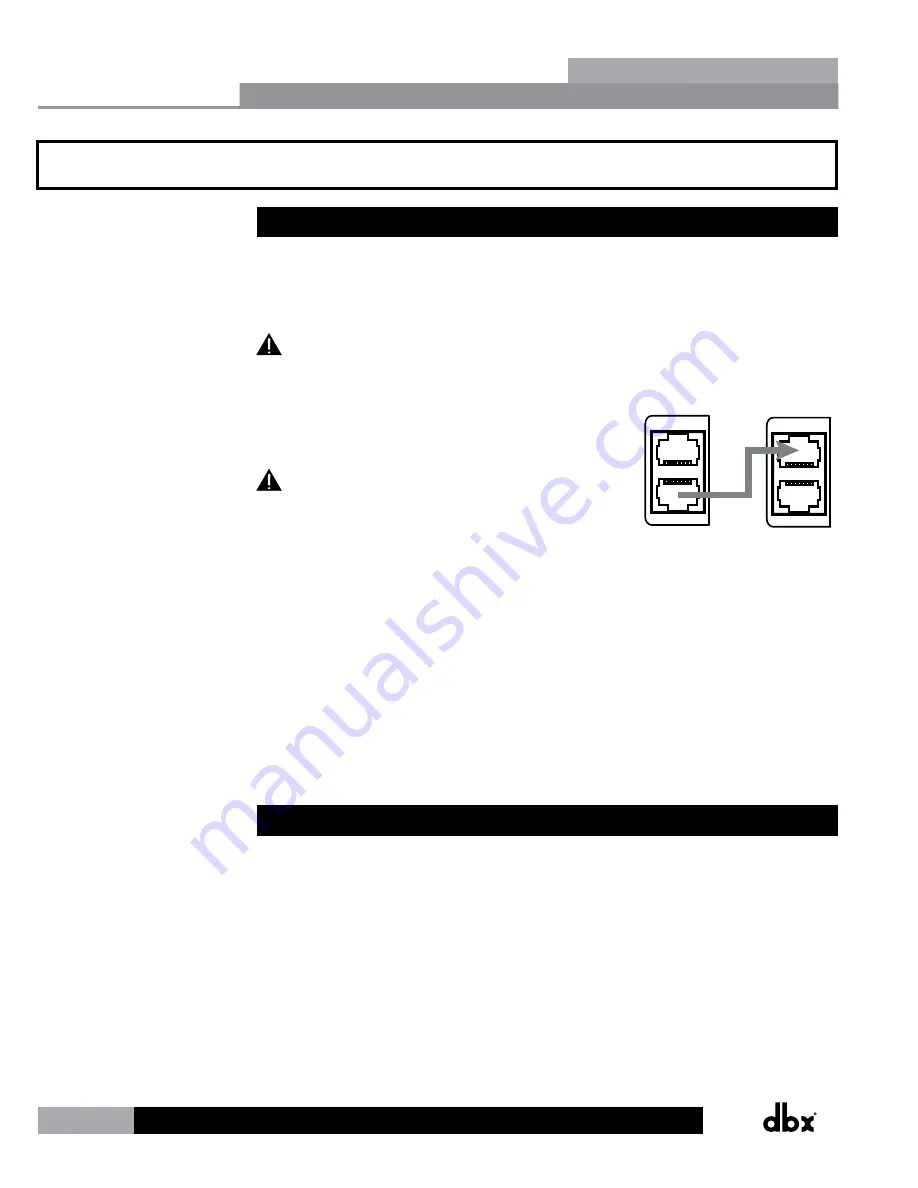
Simply connect a short straight-through Cat 5 cable from 
the Link Output RJ-45 connector of the device sending the 
signals, to the Link Input RJ-45 connector of the device 
receiving the signals.

 The cable length of the linking cable must not 

exceed 25’! Linking more than 3 ZonePROs is typically not 
recommended, as systems of this size generally require 
processors with a more sophisticated feature set.

LINK INPUT

LINK OUTPUT

LINK INPUT

LINK OUTPUT

Sending

ZonePRO

Receiving

ZonePRO

The analog input signals are routed directly to the Link Output connector. Therefore, the 
program material coming out of the Link Output has not been processed by the DSP and when 
connected to another ZonePRO’s Link Input, both devices are processing the same program 
material. 

The Link Input connector is routed directly to the input circuitry. This means that when using 
the Link Bus, any inputs sent down the Link Bus and received at a ZonePRO’s Link Input will 
render those corresponding input jacks unusable on the receiving ZonePRO. If a source were to 
be connected to any of the receiving ZonePRO’s corresponding inputs, this would be akin to 
connecting two sources to the same input jacks and doing so may cause distortion or damage 
to the processor.

5.2 Jumpers

If there are signals that you do not want to send or receive through the Link Bus you can 
open those connections in the Cat 5 cable. The RCA inputs are always active and can only be 
disconnected by opening the connections in the Cat 5 cable, but the ML1 and ML2 Euroblock 
mic/line inputs do have selection jumpers inside the device. These jumpers can be set to 
“Enabled” or “Disabled” on the “Link In” side or “Link Out” side on each ZonePRO processor. 
These jumpers come from the factory set to “Enabled”.

Link I/O

Section 5

Summary of Contents for dbx ZonePRO 1260

Page 1: ...Installation Guide Digital Zone Processors 640 640m 641 641m 1260 1260m 1261 1261m ZonePRO TM...

Page 2: ...Networking 25 6 1 Default ZonePRO Network Settings 25 6 2 Networking Overview 25 6 3 Overview of TCP IP Basics 26 6 4 Connecting via direct connect Ethernet 27 6 5 Setup of a simple isolated Ethernet...

Page 3: ...2 6 6 4 Pair Q Q Q Q Q 1260 12 6 2 8 Pair Q Q Q Q 1261m 12 6 6 4 Pair Q Q Q Q 1261 12 6 2 8 Pair Q Q Q 640m 6 4 4 2 Pair Q Q Q Q 640 6 4 2 4 Pair Q 641m 6 4 4 2 Pair Q Q Q 641 6 4 2 4 Pair 1 2 Feature...

Page 4: ...ice we recommend you refer to this manual Make sure you have correctly followed installation steps and operating procedures For further technical assistance or service please contact our Technical Sup...

Page 5: ...ON from the factory where all parts and labor will be covered up to a period of two years A Return Authorization Number must first be obtained from dbx The company shall not be liable for any conseque...

Page 6: ...ect parameters and even create automatic system changes referred to as Scene Changes Understanding the ZonePRO Designer GUI is essential for getting the most out of the ZonePRO processors After instal...

Page 7: ...ion of the dbx website for the latest information on compatible RS 232 peripherals Most ZonePRO models also allow you to communicate via Ethernet the exception being the 640 and 641 models which do no...

Page 8: ...not automatically appear proceed with these instructions 4 Go into Window s Device Manager Ports Take note of your COM port s assigned COM number shown in parenthesis If you do not see your COM port h...

Page 9: ...e and have a Status of Resolved If it does not ensure that the RS 232 cable is securely connected and that you are using the correct RS 232 cable and a compatible RS 232 peripheral If the ZonePRO devi...

Page 10: ...information relating to parameters such as source selection page steering zone volumes and mutes 2 Parameter Select Buttons 1 3 Allows selection of parameters on display 3 Data Wheel Used to edit par...

Page 11: ...t to the PC for configuration control and monitoring It can also be used for communication with a third party control system The baud rate of this port is 57600 Front and rear PC ports should not be u...

Page 12: ...S5 S3 S1 CH 6 CH 5 CH 3 CH 2 CH 1 ML 2 ML 1 CH 4 7 6 8 11 11 10 12 1 2 3 4 5 9 9 1260m 1261m Rear Panel RS 232 8 7 6 1 2 3 4 5 11 11 11 10 10 10 12 12 12 9 9 9 11 9 1 Power Connector Connect the inclu...

Page 13: ...S2 8 RCA Source Inputs Mono summed pairs of unbalanced RCA audio inputs Each pair of unbalanced RCA inputs are internally mono summed This is beneficial when your application requires mono zones Howev...

Page 14: ...3 The ZC 3 is a programmable zone controller that allows control of source selection page steering or scene selection via a four position rotary control The ZC 3 must be assigned as ID 1 and connecte...

Page 15: ...ZC 9 provides source selection control via an eight position rotary selector IN OUT INPUTS RJ45 CONNECT ONLY TO ZONE CONTROLLER INPUT RELAY SWITCH CLOSURE CONTROL VOLTAGE 5 24 VDC ZC FIRE The ZC FIRE...

Page 16: ...14 ZonePROTM The below matrix table shows a side by side comparison of the ZC s features Zone Controllers Section 4...

Page 17: ...2 2 Orange Controller 1 7 3 3 White Green Controller 2 8 4 4 Blue Controller 3 9 5 5 White Blue Controller 4 10 6 6 Green Controller 5 11 7 7 White Brown Controller 6 12 All Zone Controllers can be wi...

Page 18: ...parallel a ZC BOB must be used To wire in parallel each Zone Controller must be wired into one of the ZC BOB s numbered ports The ZC BOB s Output port is then connected to one of the ZonePRO s ZC Inp...

Page 19: ...en connecting the ZCs in parallel using a ZC BOB and the maximum cable length of the cable between the ZC BOB and ZonePRO device Diagram A Diagram B Diagram C RJ 45 8 Position RJ 45 8 Position Orange...

Page 20: ...re a ZC 4 for contact closure control using relays or SPDT single pole double throw type switches All pins on the ZC 4 must be connected Any pins not directly connected to a switch or relay should be...

Page 21: ...C to the top ZC Input port on the ZonePRO You must then program this ZC on the corresponding ZC Panel Configuration page in ZonePRO Designer s Configuration Wizard as ZC Input 2 ID 2 ZC INPUT ZC INPUT...

Page 22: ...2 3 4 5 6 7 8 9 10 ZC 1 ZC 3 A B C D SELECT A B C D A B C D SELECT A B C D A B C D SELECT A B C D A B C D SELECT A B C D A B C D SELECT A B C D A B C D SELECT A B C D ID 1 ID 2 ID 3 ID 4 ID 5 ID 6 ID...

Page 23: ...ed to control the volume of a karaoke microphone for example this is the page where you would associate a ZC volume controller to control the input gain of the karaoke mic When controlling input gain...

Page 24: ...the program material coming out of the Link Output has not been processed by the DSP and when connected to another ZonePRO s Link Input both devices are processing the same program material The Link...

Page 25: ...ng to qualified service personnel Disconnect mains power before servicing To Enable or Disable the Link Input or Link Output for the ML1 and or ML2 inputs match the jumpers to the desired positions P1...

Page 26: ...1261 Link Bus Send Receive ML1 ML2 S1 S2 S3 S4 ZC INPUT ZC INPUT OUTPUTS SOURCE MIC LINE MIC GAIN MIC GAIN MIC LINE MIC LINE PC 10 100 BaseT S PDIF INPUT LINK INPUT LINK OUTPUT R CLIP G SIGNAL CLIP R...

Page 27: ...iguration details how to add one or more ZonePRO devices to an existing Local Area Network LAN The following subsections explain how and when to connect to a remote ZonePRO using the proxy feature and...

Page 28: ...P address has two parts the NETWORK ID and the HOST ID The NETWORK ID identifies the network and the HOST ID identifies either the subnet and device or just the device if there is no subnet The subnet...

Page 29: ...ng on Run from the Window s Start Menu b Enter cmd and click OK This will bring up a command window DOS box c At the prompt enter ipconfig and press enter d Now on your screen you will see your curren...

Page 30: ...of a simple isolated Ethernet network Assumptions Using Microsoft Windows XP Vista or 7 Computer has a working Ethernet network adapter You have an Ethernet hub or switch and Ethernet cables for each...

Page 31: ...formation to restore your network settings e Select the Obtain an IP address automatically radio button f Click on the Alternate Configuration tab and make sure that Automatic private IP address is se...

Page 32: ...re that Use Ethernet is selected Click Next 5 Click Next again to enter the Address Tool It may take up to one minute for your new ZonePRO to show up in the device window 6 Select the ZonePRO from the...

Page 33: ...e has a network connection to that ZonePRO device You should be able to ping the ZonePRO from the Windows computer 2 Select Properties from the Network menu of the main ZonePRO Designer window 3 Make...

Page 34: ...R860 95 is one solution that has been tested and is both inexpensive and simple to set up It provides up to two concurrent VPN connections It works well with the built in VPN interfaces in Microsoft W...

Page 35: ...Hub Switch if used If you fail to see a link light try removing and reinserting the cable or try a different known working cable Also make sure you are using the correct type of Ethernet cable Ping Th...

Page 36: ...34 ZonePROTM Section 7 Application Guide 7 1 Restaurant Application Application Guide Section 7...

Page 37: ...ommodate changes in the venue such as a volume boost in the bar for happy hour as well as the regular volume boost in the restaurant for the lunch time rush and the dinner crowd 6 The ZC 3 in the rest...

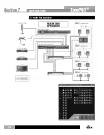
Page 38: ...36 ZonePROTM 7 2 Health Club Application Application Guide Section 7...

Page 39: ...De Esssing and EQ are used to make the paging microphone as intelligible as possible 6 The Crossover is used to separate the frequencies for the main and sub speakers in the aerobics room 7 The TV fee...

Page 40: ...38 ZonePROTM 7 3 Nightclub Application Application Guide Section 7...

Page 41: ...rea so it arrives at the same time as the acoustic signal from the nightclub 5 The restaurant receives the signal from the nightclub allowing it to be sent to the entire restaurant 6 The zone controll...

Page 42: ...ection 8 Appendix 8 1 ZonePRO 640 641 Block Diagram L R L R L R ZC Jack 1 ZC Jack 2 Link In Out Link In Out Link In Out Link In Out Link In Out Link In Out Output 1 Output 2 Output 3 Output 4 L R Appe...

Page 43: ...ZonePRO 640m 641m Block Diagram L R L R Link In Out Link In Out Output 1 Output 2 Output 3 Output 4 ZC Jack 1 ZC Jack 2 641m only Zone Pro 640m 641m Block Diagram Ethernet Link In Out Link In Out Sec...

Page 44: ...L R Link In Out Link In Out L R L R Link In Out Link In Out L R L R Link In Out Link In Out Output 1 Output 2 Output 3 Output 4 Output 5 Output 6 ZC Jack 1 ZC Jack 2 1261 only L R L R S PDIF Zone Pro...

Page 45: ...ram L R L R Link In Out Link In Out Output 1 Output 2 Output 3 Output 4 Output 5 Output 6 ZC Jack 1 ZC Jack 2 1261m only L R L R S PDIF Zone Pro 1260m 1261m Block Diagram Ethernet Link In Out Link In...

Page 46: ...ill load the new firmware version to a device connected via RS232 The receiving ZonePRO should be running Follow the directions in the PC flasher application If for some reason you are not able to upd...

Page 47: ...tory Soft Reset From ZonePRO Designer 1261 1261m 641 641m From ZonePRO Designer s program screen select Help Reset Soft Reset This sends a message to the ZonePRO to perform a Soft Reset and restart it...

Page 48: ...Bu A D Performance Type dbx Type IV conversion system Dynamic Range Line 113 dB A weighted 110 dB unweighted Type IV Dynamic Range 119 dB A weighted 22kHz BW 117 dB unweighted 22kHz BW Sample Rate 48...

Page 49: ...nce Type dbx Type IV conversion system Dynamic Range Line 113 dB A weighted 110 dB unweighted Type IV Dynamic Range 119 dB A weighted 22 kHz BW 117 dB unweighted 22 kHz BW Sample Rate 48 kHz D A Perfo...

Page 50: ...20 balanced 60 unbalanced Max Output Level 20 dBu A D Performance Type dbx Type IV conversion system Dynamic Range Line 113 dB A weighted 110 dB unweighted Type IV Dynamic Range 119 dB A weighted 22 k...

Page 51: ...120 balanced 60 unbalanced Max Output Level 20 dBu A D Performance Type dbx Type IV conversion system Dynamic Range Line 113 dB A weighted 110 dB unweighted Type IV Dynamic Range 119 dB A weighted 22...

Page 52: ...ted temperature dust and smoke can adversely affect fan life Systems exposed to these conditions should be inspected more frequently Fan replacement can be performed either at the factory or by an exp...

Page 53: ...on 8 8 Brown Ground 1 1 White Orange Voltage Reference 2 2 Orange ML1 Input 3 3 White Green ML2 Input 4 4 Blue S1 Input 5 5 White Blue S2 Input 6 6 Green S3 Input 7 7 White Brown S4 Input Zone Control...

Page 54: ...on from the X Consortium X Window System is a trademark of X Consortium Inc Berkeley based copyrights General Redistribution and use in source and binary forms with or without modification are permitt...

Page 55: ...IRECT INCIDENTAL SPECIAL EXEMPLARY OR CONSEQUENTIAL DAMAGES INCLUDING BUT NOT LIMITED TO PROCUREMENT OF SUBSTITUTE GOODS OR SERVICES LOSS OF USE DATA OR PROFITS OR BUSINESS INTERRUPTION HOWEVER CAUSED...

Page 56: ...Phone 801 566 8800 Website dbxpro com Support dbxpro com en US support dbx Professional Products is a registered trademark of HARMAN 2017 HARMAN All rights reserved ZonePRO Install Guide PN 5059565 B...

Reviews: