Harman AMX MIO-R3 Instruction Manual Download Page 10

Setup Mode

10

 Mio Modero R-3 Remote - Instruction Manual

Firmware Version

Pressing button 

5

 on the remote displays the remote and ZigBee firmware versions currently loaded on the remote. To view the 

available firmware versions, press the 

Move Up

 arrow on the scroll wheel (refer to the 
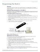
The Mio Modero® R-3

section on page 5 for 

more information) to scroll up. and pressing the 

Move Down

 arrow will scroll down. When finished, press 

Exit

 to save the changed 

firmware information and leave 

Setup

 mode.

Device ID

Pressing button 

6

 displays the device’s Device ID number. The default Device ID number is 10001, with the first "1" highlighted, 

signaling to the user that it can be changed. 
To change the Device ID number, press the 

Move Up

 arrow on the scroll wheel to scroll up. and pressing the 

Move Down

 arrow will 

scroll down. To move the cursor to the next number, use the 

Move Left

 or

 Move Right

 arrows on the scroll wheel to change 

positions.
After all numbers have been configured as desired, pressing the center button on the scroll wheel will store the entered Device ID 

into memory. After the Device ID is stored into memory, the display will return to 

Setup

 mode.

LED Awake Brightness

The red LEDs that backlight the Power button when the remote is awake are also used to indicate charging status. These LEDs will 

slowly blink on and off if the remote is place in the charging cradle and the Lithium-Ion battery pack is being charged. The LEDs will 

remain on when charging is complete.
Pressing button 

7

 will change the brightness of the Power LED from 

Low

, to 

Med

 and then 

High

. Pressing the button again toggles 

to the new mode. 30 seconds after selecting the mode, the menu returns to 

Setup

 mode.

LED Sleep Mode Brightness

The red LEDs that backlight the Power button when the remote is awake are also used to indicate charging status. These LEDs will 

slowly blink on and off if the remote is place in the charging cradle and the Lithium-Ion battery pack is being charged. The LEDs will 

remain on when charging is complete.
This setting controls the brightness of these LEDs when the remote is sleeping. When the remote is in 

Setup

 mode, pressing the 

8


button will toggle between four brightness settings - 

Sleep

Low

Med

, and 

Off

. Pressing the button again toggles to the new mode. 

30 seconds after selecting the mode, the menu returns to 

Setup

 mode.

ZigBee Extended PAN ID, Channel, and System Connection

Pressing the 

9

 button will display the current ZigBee Extended Personal Area Network (PAN) ID and channel for the device. (For 

more information on ZigBee Personal Area Networks, refer to the 

NXR-ZGW/-ZRP-PRO Operation/Reference Guide

, available from 

www.amx.com

.) In order to display the NetLinx Master IP and ZigBee gateway EUI addresses, press the 

Move Up

 arrow on the 

scroll wheel to scroll up. and pressing the 

Move Down

 arrow will scroll down. When finished, press 

Exit

 to save the Extended PAN ID 

and channel information and leave 

Setup

 mode. The display will return to 

Setup

 mode 30 seconds after releasing the 

9

 button.

Network Scan

Pressing the 

0

 button makes the Mio R-3 scan all frequencies and store all active Extended PAN IDs and Channels in memory. The 

display will show the first accessible Extended PAN ID and Channel.
To display other Extended PAN IDs and Channels found in the area, press the 

Move Up

 or 

Move Down

 arrows on the scroll wheel 

until the remote displays the desired Extended PAN ID and Channel.
To connect to a particular Extended PAN ID, pressing the center button on the scroll wheel will initiate the remote to connect to a 

network.
If no ZigBee networks were found, the display will read 

SCAN FAIL

 before returning to 

Setup

 mode. To exit the Network Scan, press 

the 

Exit

 button.

TeleText Mode

For various reasons, the standard numeric keypad for the Mio R-3 may be bypassed in favor of using the Teletext mode. This mode 

allows the central toggle wheel to be used to enter alphanumeric information, such as passwords, much like the toggle wheel on a 

phone. Pressing the 

Input

 button puts the central toggle wheel into Teletext mode. Press 

Input

 again to leave Teletext mode.

NOTE: 

When upgrading a ZigBee network from ZigBee to ZigBee Pro, the firmware upgrade necessary for ZigBee Pro will leave the Mio 

R-3 in a default Teletext mode. This may be left at any time by pressing the Input button.

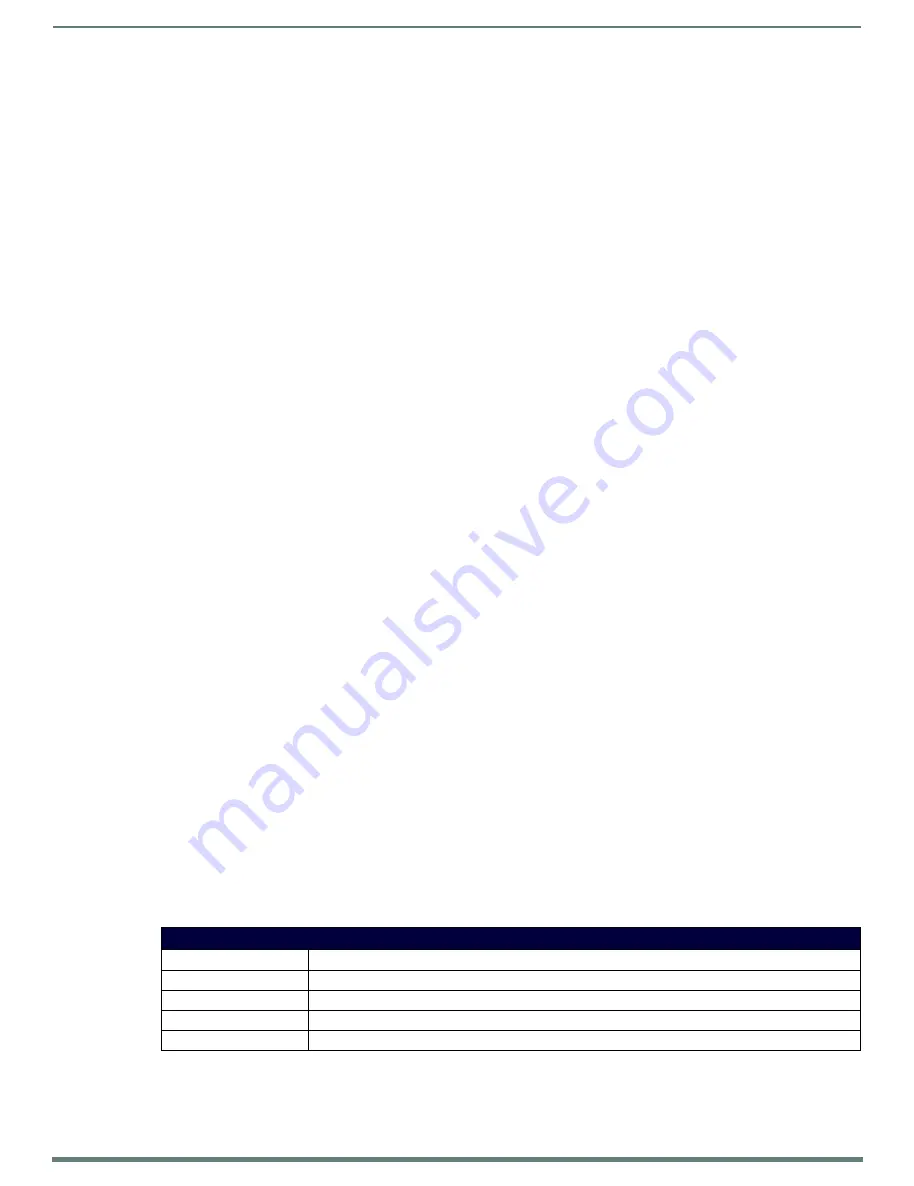
TeleText button functions

Toggle Wheel up/down

Scrolls character up/down

Toggle Wheel left/right

Moves cursor left/right between 

Last 

button

Backspace (moves cursor back one space and erases previous character)

Exit

 button

Abort (erases previously selected information without entering it)

Enter

 button

Done (submits information)

All manuals and user guides at all-guides.com

Summary of Contents for AMX MIO-R3

Page 1: ...INSTRUCTION MANUAL MIO R3 MIO MODERO R 3 REMOTE KIT MIO R3 MIO R3 CC All manuals and user guides at all guides com a l l g u i d e s c o m...

Page 2: ...they exit from the apparatus 11 ONLY USE attachments accessories specified by the manufacturer 12 USE ONLY with a cart stand tripod bracket or table specified by the manufacturer or sold with the appa...

Page 3: ...e 9 Debug Mode 9 Roaming Diagnostic Mode 9 Firmware Version 10 Device ID 10 LED Awake Brightness 10 LED Sleep Mode Brightness 10 ZigBee Extended PAN ID Channel and System Connection 10 Network Scan 10...

Page 4: ...16 UNI 16 ZAP 16 ZIGC 16 ZIGP 16 FML 17 FML S D L 17 GLY 17 JST 18 NUMD 18 REBOOT 18 SETD 18 SHO 18 SLEEP 18 SSL 18 SST 19 SWK 19 TXT 19 UNI 19 WAKE 19 ZIGC 19 ZIGP 19 Mio Remote Charging Base 20 Over...

Page 5: ...and certified as a stand alone device according to FCC Rules CFR 47 Part 15 Subpart C Contains FCC ID CWU NXR MO This device complies with Part 15 of the FCC rules Subject to the following two condit...

Page 6: ...battery connector fully within its port Mio R 3 FG148 03 Specifications Transmission Frequencies Zigbee RF wireless network IR 38 Khz IR 455 Khz Transmission Range ZigBee 100 feet 30 48m IR 38 Khz 100...

Page 7: ...R 3 into the Mio Remote Charging Base see the Mio Remote Charging Base section on page 20 Installing Custom Buttons 1 Flip and turn the device so that the buttons are facing away from you and the devi...

Page 8: ...back down on the PCB and return the unit over exposing the 6 screw points 9 Tighten the 6 screw points 10 Replace the battery door and slide the door upwards to lock it in place Patents This product i...

Page 9: ...font file to the Mio R 3 remote using the remote s program port see Using the Programming Jack on The Mio R 3 section on page 11 for details the remote must first be placed into Download mode Press 3...

Page 10: ...again toggles to the new mode 30 seconds after selecting the mode the menu returns to Setup mode ZigBee Extended PAN ID Channel and System Connection Pressing the 9 button will display the current Zi...

Page 11: ...to the port on the back of your computer 7 Configure the communication parameters in KeypadBuilder Updating Mio R 3 Firmware Updating firmware in the Mio R 3 is also done through the programming jack...

Page 12: ...126 166 206 S REV u 7 47 87 127 167 207 REC p 8 48 88 128 168 208 Power Symbol 9 49 89 129 169 209 0 10 50 90 130 170 210 1 11 51 91 131 171 211 2 12 52 92 132 172 212 3 13 53 93 133 173 213 4 14 54 9...

Page 13: ...xample SEND_COMMAND Panel FML 1 S Sets dynamic line to a menu line FML D Sets a line of the display to a dynamic line with no level Syntax FML variable text address range D Variables variable text add...

Page 14: ...ined address range Syntax JST variable text address range new text alignment Variable variable text address range 1 the address range corresponds to the dynamic line number only one line is supported...

Page 15: ...s new text 1 20 ASCII characters Default string is SLEEP Example SEND_COMMAND Panel SSL KeyPad Sleep Sends the string KeyPad Sleep to the master at time of sleep SST Sends a string to the master upon...

Page 16: ...the six devices returns to default and all parameters that can be set in Setup Mode are reset to their default value ZAP MENU Sets the text displayed on the LCD for the six devices to the default valu...

Page 17: ...set the Text Field on the R3 to dynamic FML D L Sets a line of the display to a dynamic line with a level Syntax FML variable text address range D L Variables variable text address range 1 the addres...

Page 18: ...ntax SETD deviceNum Example SETD 10020 SHO Show or hide text with a set variable text range Syntax SHO variable text address range command value Variables variable text address range 1 the address ran...

Page 19: ...tate new text 1 50 ASCII characters Example SEND_COMMAND Keypad TXT 1 Test Only Sends text to variable text line on display Note You must send an FML command before sending variable text to an R3 remo...

Page 20: ...Overview The Mio remotes are complemented with a Mio RCC charging base FG147 02 FIG 5 Mio RCC Charging Base FIG 6 Mio Remote Charging Base Top and Bottom view Insert MIO R3 front Charging contacts To...

Page 21: ...ote blinks red to indicate it is charging and illuminates solid red when it is done Full charge cycle for a depleted battery is approximately 3 hours Mio RCC FG147 03K with Base FG147 02 Specification...

Page 22: ...ility for errors or omissions AMX also reserves the right to alter specifications without prior notice at any time The AMX Warranty and Return Policy and related documents can be viewed downloaded at...

Reviews: