Harman Allure50 Installation Manual Download Page 16

Harman®  •  Allure50 Installation Manual_R2  •  2016 - ___ •  09/16

16

3-90-888000i

C. Venting & Use of Elbows 

continued

Note:

 When the amount of vertical pellet vent pipe in the system exceeds 15 feet, 4” pellet vent pipe should be used.

Note:

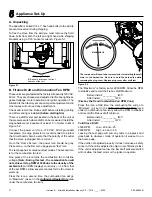
 Equivalent Venting Length decreases as altitude increases.

Example:

A unit with an EVL of 13, is to be installed at an altitude 

of 3,000 feet above sea level.
From the chart to the left, at 3,000 feet of altitude, the 

maximum  permissible  equivalent  venting  length  is  26 

feet. Therefore this would be an acceptable installation 

with no need to change the combustion blower fan.
However, if the same unit (EVL 13)was  to be installed 

an altitude of 9,000 feet above sea level, the installation 

would no longer be acceptable and the equivalent vent 

length of the pipe would have to be reduced for proper 

unit operation.

•  Long runs of flex or PL vent pipe installed directly vertical from the flue stub may require more frequent cleaning due to 

fly ash falling off inside and collecting directly above the combustion blower outlet.

•  4" stainless steel flex vent piping is only allowed for use in masonry fireplaces and chimneys or factory built wood- 

burning fireplaces with Class A metal chimneys.

•  All pellet vent pipe must be secured together either by means provided by pipe manufacturer or by 3 screws at each joint.
•  Use only the specified venting components. Use of any other components will void the product warranty and may pose 

a hazard.

•  Do Not Install a Flue Damper In The Exhaust Venting System of This Appliance.
•  DO NOT CONNECT THIS UNIT TO A CHIMNEY FLUE SERVING ANOTHER APPLIANCE.
•  Simpson DuraVent PelletVent Pro Harman®Adapter Part #3PVP-ADHB and PelletVent Pro Harman®Adapter Increaser 

Part #3PVPX4ADHB are highly recommended to be installed on the starter collar to insure a proper pipe connection to 

the unit.

• 

INSTALL VENT AT CLEARANCES SPECIFIED BY THE VENT MANUFACTURER

•  Use silicone to create an effective vapor barrier at the location where the chimney or outside air ducting passes through 

to the exterior of the structure

0 Ft

5 Ft

5 Ft

10,000

9,000

8,000

7,000

6,000

5,000

4,000

3,000

5 Ft

0 Ft

10 Ft

Altitude

10 Ft

15 Ft

20 Ft

25 Ft

30 Ft

5 Ft

0 Ft

15 Ft

Equivalent V

ent Length (EVL)

Maximum Horizontal Run

Summary of Contents for Allure50

Page 1: ... fire Check building codes prior to installation Installation MUST comply with local regional state and national codes and regulations Contact local building or fire officials about restrictions and installation inspection requirements in your area To obtain a French translation of this manual please contact your dealer or visit www harmanstoves com Pour obtenir une traduction française de ce manu...

Page 2: ...cation and Vent Information A Vent Termination Minimum Clearances 10 13 B Chimney Diagram 14 C Venting Use of Elbows 15 16 D Outside Air 17 E Locating Your Appliance and Chimney 18 F Draft 18 G Negative Pressure 18 H Avoiding Smoke Odors 19 I Fire Safety 20 J Inspect Appliance Components 20 5 Appliance Setup A Unpacking 21 B Firebox Draft and Combustion Fan RPM 21 6 Reference Materials A Safety Re...

Page 3: ...wall roof flashing installed and sealed ________________________________ Terminations installed and sealed ________________________________ Electrical Section 1 Pg 4 120VAC unswitched power provided to the appliance ________________________________ Appliance Setup Section 5 Pg 21 22 All packaging and protective materials are removed ________________________________ Accessories installed properly _...

Page 4: ...herwise operate this wood heater in a manner inconsistent with operating instructions in this manual This wood heater needs periodic inspection and repair for proper operation It is against federal regulations to operate this wood heater in a manner inconsistent with operating instructions in this manual E Electrical Codes 115 VAC 60 Hz Start 3 5 Amps Run 2 5 Amps D BTU Efficiency Specifications 1...

Page 5: ...ulations Consult insurance carrier local building inspector fire officials or authorities having jurisdiction over restrictions installation inspection and permits It is a good idea to plan your installation on paper using exact measurements for clearances and floor protection before actually beginning the installation Consideration must be given to Safety convenience traffic flow Placement of the...

Page 6: ...component not approved by Hearth Home Technologies Install parts or components not Listed or approved Disable safety switches Improper installation adjustment alteration service or maintenance can cause injury or property damage For assistance or additional information consult a qualified installer service agency or your dealer Hearth Home Technologies disclaims any responsibility for and the warr...

Page 7: ...ation Manual_R2 2016 ___ 09 16 7 3 90 888000i 3 Clearances Figure 3 1 A Appliance Dimension Diagram Dimensions are actual appliance dimensions Use for reference only 39 7 8 38 3 4 21 1 4 1 3 8 26 5 8 13 3 4 6 1 38 3 4 8 9 16 ...

Page 8: ...s shown in Figure 3 2 Note that the clearances shown are minimum for safety but do not leave much room for access when cleaning or servicing Please take this into account when placing the stove When installing the unit into an alcove it is important to consider the required clearances listed below 42 High 33 1 4 Wide Height 51 Width 36 1 4 Depth 24 B Non Combustible Materials Specification Materia...

Page 9: ...llowed 1 The unit must be bolted to the floor This can be done using an appropriate fastener for the application 2 The unit must be connected to an outside combustion air inlet Proper supports and spark arresters must be considered when installing venting See Termination Location and Vent Information Section D 3 Floor protection and clearances must be followed as shown 4 Unit must be grounded to t...

Page 10: ...nt venting for normal operation but requires the stove to be installed farther from the wall The vertical portion of the vent should be three to five feet high and at least 1 from a combustible wall This vertical section will provide natural draft in the event of a power failure Seal pipe joints with silicone or aluminum tape in addition to the sealing system used by the manufacturer If the stove ...

Page 11: ...place chimney Figure 4 4 This method provides excellent venting for normal operation This method also provides natural draft in the event of a power failure If the chimney condition is questionable you may want to install a liner as in method 5 In some places in the US and Canada it is required that the vent pipe extend all the way to the top of the chimney The chimney should be inspected and clea...

Page 12: ...et vent pipe fittings Seal pipe joints with silicone or aluminum tape in addition to the sealing system used by the manufacturer Pipe size should be increased to 4 using this method 6 Installing into an existing chimney Figure 4 6 w Full liner This method provides excellent venting for normal operation This method also provides natural draft in the event of a power failure In some places in the US...

Page 13: ...LT CAUTION 12 min wall to outlet 36 min clearance to any combustible material Figure 4 7 Figure 4 8 Figure 4 9 Area within dotted circle represents the minimum clearance to combustible materials such as shrubbery mulch or tall grasses 12 min above ground level Minimum flue vent configuration It is recommended that outside air be installed with this venting configuration Smoke spillage may be possi...

Page 14: ...porch deck or balcony is fully open on a minimum of 2 sides beneath the floor See NFPA 211 for more installation clearance reductions when using outside air Where passage through a wall or partition of combustible construction is desired the installation shall conform to CAN CSA B365 if in Canada WARNING Venting terminals must not be recessed into a wall or siding Only PL vent pipe wall pass throu...

Page 15: ...e Example First Floor Installation A unit is to be installed using 3 Pellet Pipe with 3 feet of horizontal pipe a Tee 10 feet of vertical pipe a 90 elbow and a termination cap The equivalent vent length is 3 ft of Horizontal Pipe 1 x 3 EVL 3 EVL 90 Elbow or Tee 1 x EVL 5 EVL 10 ft of Vertical Pipe 10 x 5 EVL 5 EVL 90 Elbow or Tee 1 x EVL 5 EVL Termination Cap 0 EVL Equivalent Vent Length 18 EVL In...

Page 16: ...e combustion blower outlet 4 stainless steel flex vent piping is only allowed for use in masonry fireplaces and chimneys or factory built wood burning fireplaces with Class A metal chimneys All pellet vent pipe must be secured together either by means provided by pipe manufacturer or by 3 screws at each joint Use only the specified venting components Use of any other components will void the produ...

Page 17: ...e total house demand House demand may consume some air needed for the stove especially during a power failure It may be necessary to add additional ventilation to the space in which the pellet appliance is located Consult with your local HVAC professional to determine the ventilation demands for your house To install outside air use 3 non combustible flex pipe There is a break away hole on the rea...

Page 18: ... in the home are closed Record the second draft reading _______ If the second reading is more than 05 lower than the first reading check for possible restrictions or the need for outside air For more information on the draft test procedure refer to Appliance Set Up Section C DO NOT CONNECT THIS UNIT TOACHIMNEY FLUE SERVICING ANOTHER APPLIANCE DO NOT CONNECT TO ANY AIR DISTRIBUTION DUCT OR SYSTEM M...

Page 19: ...rough combustible walls and ceilings Be sure to use a starting collar to attach the venting system to the stove The starting collar must be secured to the flue stub with at least three screws and sealed with high temp silicone caulking 4 stainless steel flex vent piping is only allowed for use in masonry fireplaces and chimneys or factory built wood burning fireplaces with Class A metal chimneys P...

Page 20: ...aintain regularly Conveniently locate a ClassAfire extinguisher to contend with small fires In the event of a hopper fire Evacuate the house immediately Notify fire department J Inspect Appliance Components Remove appliance and components from packaging and inspect for damage Report to your dealer any parts damaged in shipment Read all the instructions before starting the installation Follow these...

Page 21: ...ion fan to full line voltage Note During this test the combustion fan will not achieve its top RPM of 3200 due to the density of the ambient air All RPM displays could vary 50 from that of the set RPM s Allow several minutes for the fan motor to warm up Press the icon a second time the combustion fan will go to Maximum as set in the Authorized Dealer Only area under the combustion fan icon The Max...

Page 22: ... as the stove Clothing and other flammable materials should not be placed on or near this stove Installation and repair of this stove should be done by a qualified service person The appliance should be inspected before use and at least annually by a qualified service person More frequent cleaning may be required It is imperative that control compartments burners and circulating air passageways of...

Page 23: ...E CAPACITOR SKY BLUE BLACK SKY BLUE YELLOW PRESSURE SWITCH GREEN YELLOW ANY IEC POWER CORD RATED FOR 120 VAC 10 AMP 250 VAC 10 AMP SKY BLUE YELLOW SKY BLUE BROWN GREEN YELLOW LINE FILTER INSIDE BURNPOT IGNITER ELEMENT COMBUSTION MOTOR SENSOR ALLURE ABSOLUTE 63 DISTRIBUTION BLOWERS CABLE GOING TO TOUCH CONTROL GROUND TO STOVE BODY BACKUP ESP G R E E N Y E L L O W GROUND TO FEEDER BODY DARK BLUE SKY...

Page 24: ... in U S A Copyright 2015 Harman a brand of Hearth Home Technologies Inc 352 Mountain House Road Halifax PA 17032 www harmanstoves com Please contact your Harman dealer with any questions or concerns For the location of your nearest Harman dealer please visit www harmanstoves com ...

Reviews: