


Harman® • Allure50 Installation Manual_R2 • 2016 - ___ • 09/16
14
3-90-888000i
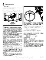
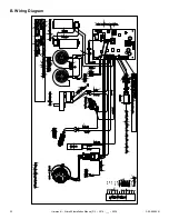
B. Chimney Diagram
V
=Vent Terminal
A
=Air Supply Inlet
=Area where termination is not permitted
Door
Sidewalk
Fixed
Closed
Openable
Openable
Fixed
Closed
Inside Corner
Detail
Porch or
Openable
Deck
or Fixed
Requirements for Terminating the Venting
Figure 4.10
I. The clearance to service regulator vent outlet must be a
minimum of 6 feet.
J. The clearance to a non-mechanical air supply inlet to the
building or the combustion air inlet to any other appliance
must be a minimum of 48”.
K. The clearance to a mechanical air supply inlet must be a
minimum of 10 feet.
(
with outside air installed, 6 feet
)
L. The clearance above a paved sidewalk or a paved
driveway located on public property must be a minimum
of 7 feet.
M. The clearance under a veranda, porch, deck or balcony
must be a minimum of 12 inches.
(B. also)
The clearance to vegetation and other exterior
combustibles such as mulch is 36” as measured from
the center of the outlet or cap. This 36” radius continues
to grade.
Certain Canadian and or Local codes or regulations may
require different clearances.
A vent shall not terminate directly above a side-walk or
paved driveway which is located between two single family
dwellings and serves both dwellings.
Only permitted if veranda, porch, deck, or balcony is fully
open on a minimum of 2 sides beneath the floor.
See NFPA 211 for more installation clearance reductions
when using outside air.
Where passage through a wall, or partition of combustible
construction is desired, the installation shall conform to
CAN/CSA-B365. (if in Canada)
WARNING
!
Venting terminals must not be recessed into a wall
or siding.
Only PL vent pipe wall pass-through and fire stops
should be used when venting through combustible
materials.
Always take into consideration the effect the prevailing
wind direction or other wind currents will cause with
flyash and /or smoke when placing the termination.
In addition, the following must be observed:
A. The clearance above grade must be a minimum of 12”.
B. The clearance to a window or door that may be opened must
be a minimum of 48” to the side, 48” below the window/door,
12” above the window/door.
(
with outside air installed, 9”
to side and below
)
C. A 12” clearance to a permanently closed window is
recommended to prevent condensation on the window.
D. The vertical clearance to a ventilated soffit located above the
terminal within a horizontal distance of 2 feet (60 cm) from
the center-line of the terminal must be a minimum of 18”.
E. The clearance to an unventilated soffit must be a minimum
of 12”.
F. The clearance to an outside corner is 11” from center of pipe.
G. The clearance to an inside corner is 12”.
H. A vent must not be installed within 3 feet (90 cm) above a
gas meter/regulator assembly when measured from the
horizontal center-line of the regulator.