19
PF100
NOTE: KEEP THE FAN/LIMIT CONTROL
INSTRUCTIONS WITH THE OWNERS
MANUAL FOR FUTURE REFERENCE.
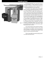
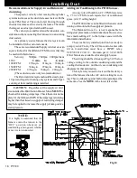
1. The Fan Control must be placed in the discharge
plenum approximately 11 inches above the discharge open-
ing of the furnace as close to center as possible.
Note:
The best place is on the same side as the ash
door because of ease of access. See Fig. 35.
Note:
Care must be taken when installing the Fan
Control when an air conditioning A Coil is used. The Fan
Control
must
always be installed below the A Coil in low
plenum installations.
2. Install the flex and wiring.
3. Make sure that the flue venting will not interfere
with the flex to the Fan Control.
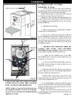
4. Pry out one of the bottom knockouts of the Fan
Control. Install the 90 degree flex connector as shown in
Fig. 36. One of the locknuts stays on the outside of the
box and one goes on the inside to tighten the connector
into place. This allows for maximum room for the wires
around the switches.
5.
REMOVE THE COPPER JUMPER BE-
TWEEN THE LIMIT AND CONTROL
SWITCHES. (It is not needed.)
Figure 36 shown with
copper jumper that has already been removed.
6. Connect the two VIOLET wires to the FAN
CONTROL switch. ( It doesn’t matter which wire is on
which screw). See Fig. 36.
7. Connect the WHITE and SKY BLUE wires to
the LIMIT switch. ( It doesn’t matter which wire is on
which screw). See Fig. 36.
8. Make sure that all of the wires are out of the way
when closing the cover. ( Excess twisting and pinching of
the wires could cause a short circuit.)
9. HIGH LIMIT setup is simple, just rotate the high
limit pointer clockwise until it is against the tamper-proof
screw. (Never adjust this screw)
10. FAN CONTROL setup: Move both fan control
pointers together until they touch, then rotate both pointers
together until the gap between them is directly over the
middle 0 of 100. See Fig 36.
Note:
This is the best fan control position we have
found during factory testing. These fan control limits can
be adjusted if desired.
Fig. 35
FAN/HIGH LIMIT CONTROL
Installation & Set-up
High limit fan control
NOTE: If fans are used in the fuel storage area,
they should be installed so as not to create negative
pressures in the room where the solid-fuel-burning
appliance is located.
High Limit
Setpoint
CONTROL
Fig. 36
Fan Control
Setpoint
LIMIT
Locknuts outside and inside
Installation
Summary of Contents for PF-100 Furnace
Page 11: ...11 PF100 Fig 19 Venting Configuration Graph Venting ...
Page 35: ...35 PF100 Feeder Parts ...
Page 40: ...40 PF100 Testing Label ...


