background image

7

PC 45 Corn/Pellet Stove

Venting

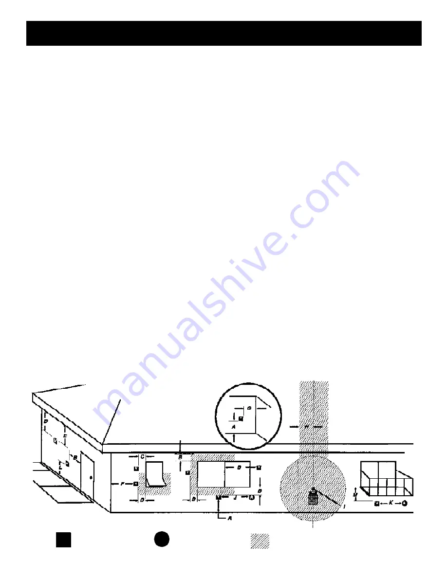
Requirements for Terminating the Venting

WARNING: Venting terminals must not be re-

cessed into a wall or siding.

NOTE:  Only  PL  vent  pipe  wall  pass-throughs

and fire stops should be used when venting through
combustible  materials.

NOTE: Always  take into consideration  the ef-

fect  the prevailing wind direction or other wind cur-
rents will cause with flyash and /or smoke when plac-
ing the termination.

In addition, the following must be observed:

A. The clearance above grade  must be a mini-

mum of 18".

1

B. The clearance to a window or door that may

be  opened must  be  a minimum  of  48"  to the  side,
48" below the window/door, and 12" above the win-
dow/door.

1

with outside air installed, 18” 

)

C. A  12"    clearance  to  a  permanently  closed

window  is  recommended to prevent condensation
on the  window.

D. The vertical clearance to a ventilated soffit

located  above  the  terminal  within  a  horizontal  dis-
tance of 2 feet (60 cm) from the center-line of the
terminal  must be a minimum of 18".

E. The clearance to an unventilated soffit  must

be a minimum of 12".

F.  The  clearance  to  an  outside  corner  is  11"

from center of pipe.

G. The clearance to an inside corner is 12".
H.  A vent must not be installed within 3 feet (90

cm)  above  a  gas  meter/regulator  assembly  when
measured from the horizontal center-line of the regu-
lator.

1

I. The clearance to service regulator vent outlet

must be a minimum of 6 feet.

1

J. The clearance to a non-mechanical air sup-

ply inlet to the building or the combustion air inlet to

any other appliance must be a minimum of 48”.

1

K.  The  clearance  to  a  mechanical  air  supply

inlet must be a minimum of 10 feet.

1

(

with outside air installed, 6 feet 

)

L. The clearance above a paved sidewalk or a

paved driveway located on public property must be
a minimum of  7 feet.

1,2


M. The clearance under a veranda, porch, deck

or balcony must be a minimum of 12 inches.

1,3

NOTE:  The clearance to vegetation and other

exterior combustibles such as mulch is 36” as mea-

sured from the center of the outlet or cap. This 36”

radius  continues  to  grade  or  a  minimum  of  7  feet
below the outlet.

1

Certain Canadian and or  Local codes or regu-

lations may require different clearances.

2

A vent shall not terminate directly above a side-

walk  or  paved  driveway  which  is  located  between
two  single   family  dwellings  and  serves  both  dwell-
ings.

3

Only permitted if veranda, porch, deck, or bal-

cony is fully open on a minimum of  2 sides beneath
the floor.

NOT E:  Where  passa ge  t hrough  a  w all,  or
partition of combustible construction is desired,
the installation shall conform to CAN/CSA-B365.
(if in  Canada)

V

A

Vent terminal

Air supply inlet

Fixed

Closed

Openable

Openable

Fixed

Closed

Inside  Corner

Detail

Area  where terminal  is not  permitted

Summary of Contents for PC 45

Page 1: ...FETY FOLLOW INSTALLATIONDIRECTIONS CONTACT LOCAL BUILDING OR FIRE OFFICIALS ABOUT RESTRICTIONS AND INSTALLATION INSPECTION REQUIREMENTS INYOUR AREA CONTACT YOUR LOCAL AUTHORITY SUCH AS MUNICIPAL BUILD...

Page 2: ...2 PC 45 Corn Pellet Stove...

Page 3: ...Sidewinder Burn Pot allows corn to be burned from three days up to a week without cleaning depending on the corn s moisture level and burn rate Automatic Ignition allows you to fill the hopper set yo...

Page 4: ...cover panels are removed from the stove to make it easier to get at the hold down bolts The rear cover panels are packed inside the hopper and should be installed on the stove as shown It is recommend...

Page 5: ...o clock position Does the door rope compress If not loosen the set screw turn the paw bolt one more turn into the door Repeat as required to achieve a tight door fit NOTE Remember to thoroughly clean...

Page 6: ...me are closed If this readingis more than 05 higher thanthe unconnected reading check for possible restrictions or the need for outside air See page 8 Mobile Home Installation When installing this uni...

Page 7: ...hen measured fromthe horizontalcenter line of the regu lator 1 I The clearance to service regulator vent outlet must be a minimum of 6 feet 1 J The clearance to a non mechanical air sup ply inlet to t...

Page 8: ...ide surface temperature to allow a clearance to combustibles of only 3 inches The sections of pipe lock together to form an air tight seal in most cases however in some cases a per fect seal is not ac...

Page 9: ...tural draft in the event of a power failure 2 Preferred method This method also provides excellent venting for normaloperation but requires the stove tobe installed farther from the wall The vertical...

Page 10: ...you may want to install a liner as in method 6 4 Installing into an existing fireplace chimney US only This method provides excellent venting for nor mal operation This method also provides natural dr...

Page 11: ...sure to use approved pellet vent pipe fittings Seal pipe joints with silicone in addition to the sealing system used by the manufacturer Pipesize shouldbe increased to 4 using this method 6 Installing...

Page 12: ...19 Fig 20 7 Installing through the ceiling vent Through the ceiling vent follow PL vent manufacturers recommendations when using wall and ceiling pass through DO NOT INSTALL A FLUE DAMPER IN THE EXHAU...

Page 13: ...with a 3 setting being the maximum setting 1 the lowest setting This set ting will vary depending on the quality of corn used When burning pellets the feed rate setting can be adjusted within the ful...

Page 14: ...s you to check the motors for operation NOTE The auger motor will not operate with the view door or ash door open NOTE The initial start upona newstove may require the corn to be purged into the burnp...

Page 15: ...l board setting The unit can only go to low burn and will remain there until it runs out of fuel or until more heat is needed and the feed rate in creases Feed rate adjustments and dial settings are t...

Page 16: ...n the Temperature Dial to the desired setting 4 Clean the burnpot and housing if necessary 5 Fill the burnpot with pellets so that the auger tube opening is covered and slopes away from the auger tube...

Page 17: ...ithin off position band except after normal shut down Blinks to indicate errors listed below Indicates power to distribution blower 6 Blinks Indicates that the control has calculated poor or incomplet...

Page 18: ...bustion Motor Speed Control Low draft only set point The small straight screwdriver slot is plastic therefore the unit can be adjusted while in operation Fig 29 Fig 30 A simple draft test should be pe...

Page 19: ...e to carry and dispose of ashes 3 Slide the ash pan back into the stove Cleaning If you have been burning corn the stove will need to be cleaned approximately once a month The amount of corn burned an...

Page 20: ...ing nut on the feeder cover and slide the cover off the threaded rod 3 Remove all fines with a vacuum Fig 37 Brush not supplied Can be found in hardware stores Fig 33 Latch closed with blower coverin...

Page 21: ...against the burnpot grate and housing 9 Install the front plate lock 10 The dirty auger extension burnpot grate and front plate just removed can now be cleaned for the next scheduled maintenance NOTE...

Page 22: ...s restricting fuel flow 4 Feed motor or draft motor has failed 5 Power failure or blown fuse SMOKE IS VISIBLE COMING OUT OF VENT 1 Air fuel ratio is too rich A Feed rate too high B Draft too low cause...

Page 23: ...Mounting Bolts 3 30 1311812513 Air Pump 3 20 02679 Air Pump Mounting Hardware BHSCS 8 32 x 1 4 3 30 3108320252 3 8 MPT x 1 4 Barb Brass Inlet Fitting 3 10 724203 Pusher Arm Mtng Bolts 4 3 30 22520050...

Page 24: ...all the hold down clips and tighten with bolts as shown on page 5 To install ash lip trim simply slide the trim over the ash lip and into the groove on the trim Gold Door The gold door fig 43 is assem...

Page 25: ...or should be installed in the loca tion where you want to control the temperature NOTE Distances of more than 25 feet from the unit or in another room are not recommended The room sensor is essentialf...

Page 26: ...26 PC 45 Corn Pellet Stove PC 45 Wiring Diagram...

Page 27: ...9301 5 Single Fan Blade 3 20 40985 Combustion Blower 3 21 08639 Distribution Blower 3 21 22647 Hopper Lid Latch 3 31 199110 3 16 Rubber Washer for Hopper Lid 3 31 90131101 Power Cord 3 20 29685 Fire B...

Page 28: ...Damage and or repairs including but not limited to remote controls filters fuses knobs glass ceramic brick panels ceramic fiber afterburners door packing tile ceramic log sets paint batteries or batt...

Reviews: