background image

17

Maintenance

Removing Ashes:

1. The ashes will need to be removed before

the ash pan overflows. This will be necessary about
once a day when on a high setting and approximately
every four days when on lower settings.

2. It is recommended that the stove be cooled

down and on a #1 setting.

3. Open the ash door, remove ash pan, and

close the ash door while the ashes are being disposed
of.

4. Replace the ash pan and turn the control to

the desire setting.

Note: Make sure there are no ashes on the floor

of the ash pan area. These ashes can build up behind
the ash pan preventing the ash door from closing prop-
erly.

Ashes should be placed in a metal container

with a tight fitting lid. The closed container of
ashes should be placed on a noncombustible
floor or on the ground,  well away from all com-
bustible materials, pending final disposal. If ashes
are disposed of by burial in soil or otherwise lo-
cally dispersed, they should be retained in the
closed container until all cinders have thoroughly
cooled.

Cleaning:

The unit itself may not need to be cleaned until

1 1/2 to 2 tons of coal are burned.

The flue pipe itself may need to be checked bi-

weekly or bi-monthly for flyash buildup. Bulk coal is
usually a bit dirtier than bagged coal; therefore, it may
require more frequent checking.

The unit should not have any coal in it to pre-

form a proper cleaning.

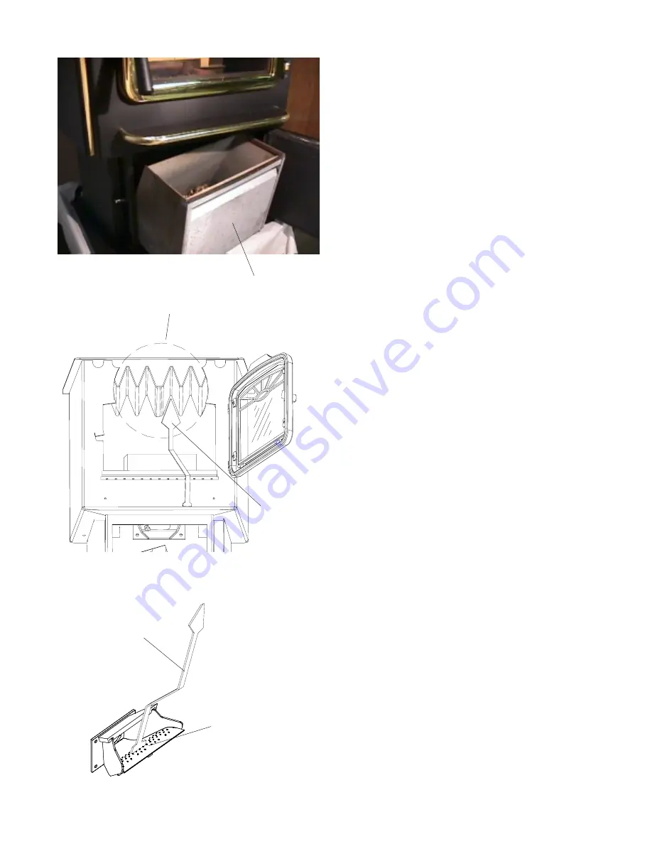
1. Clean the heat exchanger with the scraper

provided. See Figure 25.

2. Clean the inside surfaces with the end of the

scraper or use a standard wire brush.

3. Clean the burn pot and scrape the inside surfaces

to remove ash buildup.

4. Inspect the holes in the burn pot to see if they are

all open. This ensures an efficient burn when all
the holes are clean.

Scraper

Heat Exchanger Fins

      Fig. 25

Fig. 23

Scraper

ScrapeThis Area

Ash Pan

Fig. 24

Fig. 25

Summary of Contents for 44 Magnum

Page 1: ...building or fire officials about restrictions and installation inspection requirments in your area Contact your local authority such as municipal building department fire department fire prevention bureau etc to determine the need for a permit ...

Page 2: ...ELECTRICAL RATING 3 AMPS 120 VOLTS 60 HERTZ FUEL ANTHRACITE RICE COAL ALSO BITUMINOUS OF SAME SIZE INSTALL AND USE ONLY IN ACCORDANCE WITH MANUFACTURER S INSTAL LATION AND OPERATING INSTRUCTIONS CONTACT LOCAL BUILDING OR FIRE OFFICIALS ABOUT RESTRICTIONS INSTALLATION INSPECTION IN YOUR AREA U S ENVIRONMENTAL PROTECTION AGENCY THIS UNIT IS ONLY FOR BURNING COAL USE OF ANY OTHER SOLID FUEL EXCEPT FO...

Page 3: ...er Parts 20 Specifications 20 Wiring Diagram 21 Options 22 Part Numbers 24 Warranty 25 Pleasereadthisentiremanualbeforeyouinstallanduseyournew roomheater Failuretofollowinstructionsmayresultin propertydamage bodilyinjury orevendeath SAVE THESE INSTRUCTIONS Harman Stove Company 352 Mountain House Road Halifax PA17032 ...

Page 4: ...st and corrosion anditistotallytheoperator sfault Usuallyafterthe coaldriesforthreeorfourdays dependingoncon ditions itwillflowverywellandfeedproperly Feed rate will be the same as dry coal Wet Coal WARNINGS Never sleep in the same room with any coal burning stove Carbon Monoxide CO Awareness Carbon monoxide referred to as CO is a col orless odorless gas that is produced during com bustionofcoalan...

Page 5: ...dfromthestove to make it easier to get at the hold down bolts The rear cover panels are packed inside the hop per and should be installed on the stove as shown This can be done before or after the stove is in place Firebrick Install the firebrick vertically on the angle above the burnpot See Figure 2 Flame Guide Installthecastironflameguideontopoftheburn pot and make sure it is fully seated agains...

Page 6: ...ndtightenwithboltsasshown Installdooronstovewithhingepins Install door handle as shown on the diagram NOTE With the flat surface of the paw bolt to the in side of the door Turnthepawbolt in forapproximately17turns Turn the brass elbow onto the paw bolt approxi mately5 turns Align the set screw with the flat spot on the paw andtighten After attaching the door handle close and latch the door by turn...

Page 7: ...enplac ingthestove Connect the power cord to a 120 V A C 60Hz grounded receptacle 6 Fig 6 6 16 8 5 1 6 With Side Shields Without Side Shields FLOOR PROTECTOR FLOOR PROTECTOR FLO O R PRO TECTO R 10 1 2 Fig 8 10 1 2 With or Without Side Shields Fig 7 WARNING If draft is at 00 carbon monoxide may escape into the room Too much carbon monoxide can kill you Checking Draft Connect a draft meter to the dr...

Page 8: ...N SLEEPING ROOM WARNING The stove is hot while in operation Keep children clothing and furniture away Contact may cause skin burns CAUTION Installing Into An Existing Chimney Thechimneyconnectorshouldextendintothechim neyflushwiththeinsideasshownabove Fig 9 Installing Into An Existing Chimney and Adding a Liner If the chimney condition is questionable or does notprovideenoughdraft youmaywanttoinst...

Page 9: ...neyshould be5 diameter In this method a cap should also be installed to keeptherainfromenteringthechimney Installing into an existing chimney In this method a cap should also be installed to keeprainfromenteringthechimney Thechimneycon necter must extend up through the damper area and be sealed to prevent draft leakage Onedisadvantageofthismethodisthatitisharder toclean theventpipe therefore there...

Page 10: ...ctions exactly Use a 5 or 6 inch manufactured type HTchimneywitharatingof1000degreesfahrenheitor more Use only the manufacturer s parts do not use makeshiftinstallationtechniques Allprefabricatedchim neys must be tested to either the U S or Canadian high temperature standards UL 103 or ULC 629 Minimumclearancesaresetbythechimneymanu facturer Be sure to use the minimum clearance to combustablesthat...

Page 11: ...ich may influence the design and placement of your ventingsystem TheHarman44Magnum maybeinstalledwith 150 mm 24 gauge chimney connector pipe The size of the connector should correspond to the size of the fluecollaropening Donotusemakeshiftcompromises No part of the chimney connector may pass through an attic or roof space closet or other concealed space or through a floor or ceiling Whenever possi...

Page 12: ...e con nected to 1 a prefabricated chimney complying with the requirements for Type HT chimneys in the StandardforChimneys Factory Built Residential Type and Building Heating Appliances UL 103 or 2 a code approved masonry chimney with a flue liner InCanada the44Magnumislistedforuse withprefabricatedchimneystestedandlistedtothe high temperature 650 degrees C chimney stan dard ULC S 629 or with a cod...

Page 13: ...urfaceofthechimneyliner and both must be firmly cemented in place with refractory cement A thimble is a masonry pipe whichisinsertedthroughthechimneywall andis frequentlythepreferredmethod abreechpipeisa piece of steel pipe used the same way In Canada abreechpipehasridgesorprotrusionstolockit firmlyintotherefractorycement Ineithercase the chimney connector vents to the chimney through thethimbleor...

Page 14: ...e remaining holes See Figure 17 Wood pellets are shown in Figure 17 4 Add more DRY coal around the starting material but not covering it See Figure 18 Turning the knob passed the OFF position starts the combustion blower and makes the stove ready to light The distributionblowerandfeedmotorwillalsorunfor one minute or less just to let you know they are operational 5 Light the fire close all doors a...

Page 15: ...ional When a thermostat is connected to the stove it controls the heat output When the thermostat calls for heat the feed rate and blower go to max just like in Turbo range When the thermostat is satisfied the feed rate and blower speed drop to the levels set on the di als OFF When the Feed Rate dial is turned to the OFF position the fire will slowly die and go out When the stove cools down enough...

Page 16: ... increases the feed rate while turning it counterclockwise decreases it Al waysstopwiththeadjusterhandlepointingdown Fine Tune Feed Adjuster Shown with Covers Removed Thermostat Terminals Low Combustion Air Fine Tune Adjustment Thisadjustmentshouldonlybemadebyanautho rized Harman dealer using a draft meter to check re sults TheLowCombustionAirAdjustmentissetatthe factoryintheminimumposition Thisse...

Page 17: ...blematerials pendingfinaldisposal Ifashes are disposed of by burial in soil or otherwise lo cally dispersed they should be retained in the closedcontaineruntilallcindershavethoroughly cooled Cleaning The unit itself may not need to be cleaned until 1 1 2 to 2 tons of coal are burned The flue pipe itself may need to be checked bi weeklyorbi monthlyforflyashbuildup Bulkcoalis usuallyabitdirtierthanb...

Page 18: ...oves up and down in front of the burnpot The breakerhasteethonitthatbreakanyklinkers lumpsof ash andpreventanyashjamming Thisallowsthestove to be much shorter front to back Soot Build up Soot residue accumulates on the flue lining as the products of combustion combine with moisture This occurs when coal is burned When coal is ignited the soot residue creates an extremely hot fire During the heatin...

Page 19: ...t enough the feed motorwillnotstart 3 A foreign object may be in the hopper preventing theflowofcoal 4 The feed motor has failed 5 The control board has failed Reasons for Sulfur Smell or Carbon Monoxide Detector Sounding 1 Chimney draft is too low Check chimney and chimneyconnecter 2 One or both of the doors are open 3 Fluepipemightbeblockedwithflyash Reasons the Fire Has Gone Out 1 No fuel in ho...

Page 20: ...6 BEARING RETAINER 2 00 04035 CAM BEARING BOLT 3 30 1371608713 CAM BEARING 3 31 3014 CAM BLOCK 2 00 00153 GEAR MOTOR 3 20 08653 MOTOR MOUNT 2 00 01534 RUBBER GROMMET 3 31 2761 CAM TO AUGER BOLT 3 30 1252007514 AUGER MTNG BOLTS 2 3 30 1311812513 AUGER ASSY 3 50 00365 PUSHER ARM WELDMENT 1 10 08657 PILLOW BLOCK BEARING 2 3 30 3614087 5 16 WINGNUT 3 30 8131181 CAST COVER ASSY 1 10 00894 PUSHER ARM MT...

Page 21: ...21 Wiring Diagram ...

Page 22: ... thehold downclipsandtightenwithboltsasshownon page 5 Toinstallashliptrim simplyslidethetrimoverthe ash lip and into the groove on the trim Gold Door Thegolddoorisassembledandinstalledthesame as the standard door Refer to page 5 Be careful not to scratch the glass Remember to clean the gold before startingafireinthestove Toinstallashliptrim simplyslidethetrimoverthe ash lip and into the groove on ...

Page 23: ...rethefeedrate is set Installing A Thermostat Thethermostatshouldbemountedinacentrallo cation Avoidisolatedroomswithpooraircirculation Run the thermostat wire available at most hard ware stores from the thermostat to the rear of the unit anduptothethermostatterminalsonthecontrolboard See Fig 21 on page 16 Disconnect power before accessing control board The control board can be tilted out at the top...

Page 24: ...DE N D ONLY 3 20 00744 THERMISTER PROBE 3 20 04077 44M N D CIRCUIT BOARD 3 20 08653 FEEDER GEARMOTOR 2RPM 3 20 12080 THERMOSTAT LOW VOLTAGE 3 21 60994993 DISTRIBUTION BLOWER 3 21 70219720 COMBUSTION BLOWER 3 30 625202501 1 4 20 X 2 1 2 HANDLE BOLT 3 31 00968 CONTROL KNOB WHITE ON BLACK 3 31 00982 CONTROL KNOB SHAFT WHITE 3 31 199110 SWELL LATCH HOPPER LID 3 31 3614087 PILLOW BLOCK 1 2 3 40 00121 B...

Page 25: ...lorreinstallation HOW TO MAKE A CLAIM Any claim under this warranty should be made to the dealer from whom this appliance was purchased Then contact is made with manufacturer giving the model and serial numbers the date of purchase yourdealer snameandaddress plusasimpleexplanationofthenatureofthedefect SHIPPING COSTS The transportation charges are as follows 1 Customerprepaysfreightbacktofactory 2...

Reviews: