Harman Kardon Harman/kardon AVR 154 Owner'S Manual Download Page 33

33

INITIAL SETUP

NOTE:

Setting the channel levels while one surround mode is

active does not carry over to other modes. After you have set
the levels satisfactorily in one mode, note the results and change
to other surround modes. For those modes that don’t reflect
your level settings, either copy the settings you obtained as 
a short cut, or re-do the procedure to determine the correct
settings for those surround modes.

Step Five – Configure Sources

This is the last step in the configuration process. In the Installation 
section, you physically connected various cables between your source
devices and the AVR. In this section, you will assign the various audio
and video inputs to their sources, ensuring that the AVR uses the 
correct connections each time you select a source.

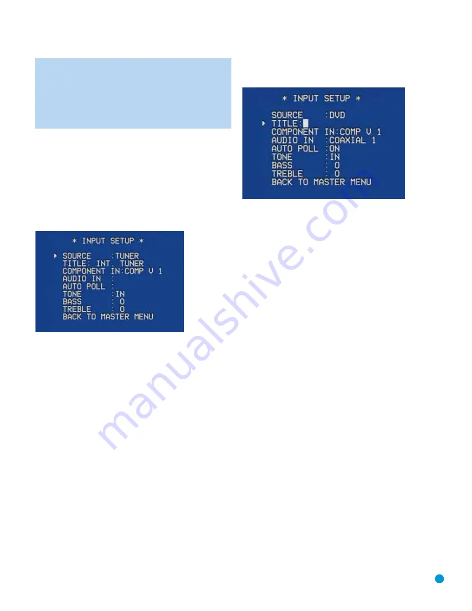
Press the OSD Button to view the Master Menu. The cursor will 
be pointing to the INPUT SETUP line, and you need only press the 
OK Button to display the Input Setup menu. See Figure 49.

Figure 49 – Input Setup Menu Screen

The first line indicates that the receiver is currently set to the tuner
source. You may hear static if the tuner is set to an unused frequency.
You will not be able to make any changes to the tuner, other than
selecting a component video input or adjusting the tone controls.
It is not recommended that you make either of these changes for 
the tuner at this time.

Press the 

Button to view the next source. The sources will be selected

in the following order: Tape, 6-Channel Inputs, AUX, Video 1, Video 2,
Video 3, HDMI 3, HDMI 2, HDMI 1, DVD and CD. Pressing the

Button selects the sources in the reverse order.

For each of these sources, you may adjust the following settings. At a
minimum, you should make sure that sources connected to any of the
component video or digital audio inputs have the correct settings. Other
settings are optional, and you may adjust them at a later time when you
have more experience with the AVR. Refer to the Table A5 worksheet in
the Appendix that you filled out during installation as you assign inputs 
to each source.

TITLE:

You may change the display name for any source (except the

tuner). Not only does this enable you to customize your system; it helps
you to select the correct source device even when you have forgotten
which physical connections you used.

Move the cursor to the TITLE line and press the OK Button. A block cur-
sor will blink. See Figure 50.

Figure 50 – Retitling a Source Input

Use the 

/

¤

Buttons to scroll through the alphabet in upper and

lower case, as well as numbers and a variety of punctuation marks.
When you have selected the desired character, press the 

Button to

move to the next space. You may also press the 

Button to leave a

blank. Press the OK Button when you have finished spelling out the 
new display name for the source.

COMPONENT IN:

If you connected the source to one of the two 

component video inputs, and the incorrect set of inputs is displayed at
this line, press the

Button to change the setting.

AUDIO IN:

See Table A2 in the Appendix for the factory default analog

or digital audio inputs assigned to each source. If you used a digital
audio connection for a source, change this setting to assign the correct
digital audio input, even if you also connected its analog audio outputs
to the receiver. Move the cursor to this line, and press the 

/

Buttons until the correct digital input appears.

AUTO POLL:

The Auto Poll feature is used when both an analog 

audio and digital audio connection have been made for one source
device. If no digital signal is available, the AVR 154 will switch to the
analog inputs for the source. This situation can occur with some cable 
or satellite television broadcasts, where some channels are broadcast
with digital audio and others with analog audio, or when a DVD player 
is paused or stopped.

For some sources, the Auto Poll feature is unnecessary and may be
undesirable, such as for a DVD player. Move the cursor to this line, and
press the 

/

Buttons until OFF appears, disabling the Auto Poll feature.

With Auto Poll turned off, the receiver will only check for a signal at the 
audio input assigned to the source.

The remaining lines in the Input Setup menu activate the tone controls,
and may be skipped at this time. We recommend leaving the tone 
controls at their factory defaults for most listening, in order to enjoy 
the sound mix created by your favorite movie and music artists.
However, if your room or speakers have unusual characteristics, or 
simply as a matter of personal preference, see the Tone Controls 
section on page 34 for more information.

You are now ready to begin enjoying your new receiver!

Summary of Contents for Harman/kardon AVR 154

Page 1: ...AVR 154 AUDIO VIDEO RECEIVER OWNER S MANUAL...

Page 2: ...ratus 11 Only use the attachments accessories specified by the manufacturer 12 Use only with a cart stand tripod bracket or table specified by the manufacturer or sold with the apparatus When a cart i...

Page 3: ...materials that may be damaged by heat or heavy objects Some surface finishes may be particularly sensitive to absorbing such marks due to a variety of factors beyond Harman Kardon s control including...

Page 4: ...4 STAPLE INVOICE HERE...

Page 5: ...Control 34 Mute Function 34 Tone Controls 35 Headphones 35 Source Selection 35 Audio Input Selection 35 Video Input Selection 36 6 Channel Direct Inputs 36 Using the Tuner 37 Recording 37 AUX Input 38...

Page 6: ...n com Note You ll need the product s serial number At the same time you can choose to be notified about our new products and or special promotions Audio Section 30 Watts x 5 five channels driven at fu...

Page 7: ...deo and component Digital audio one coaxial HDMI switching only Headphone Ease of Use On screen display with composite S video and component video 480i choice of blue or black background Two line dot...

Page 8: ...ear on the upper line while the surround mode is displayed on the lower line When the on screen display menu system OSD is in use the message OSD ON will appear to remind you to check the video displa...

Page 9: ...deo Inputs Video 3 Analog Audio Inputs Power Indicator Main Power Switch Standby On Switch Volume Remote IR Sensor Message Display Speaker Channel Input Indicators NOTE To make it easier to follow the...

Page 10: ...it to one of these jacks for improved audio performance Use only one type of digital audio connection for each source Coaxial Digital Audio Output If a source is also a digital audio recorder connect...

Page 11: ...eo Monitor Outputs AC Power Cord Front Speaker Outputs Surround Speaker Outputs 6 Channel Analog Audio Inputs Center Speaker Outputs Coaxial Digital Audio Output Optical Digital Audio Inputs 1 and 2 C...

Page 12: ...ne of these buttons to select a source device which is a component where a playback signal originates e g DVD CD cable TV satellite or HDTV tuner This will also turn on the receiver and switch the rem...

Page 13: ...port Controls Power Off Mute Input Selectors 6 Channel Input Selector Volume Controls TV Video Speaker Setup OK Numeric Keys Delay Memory Clear Preset Stations Selectors Disc Skip Macros Surround Mode...

Page 14: ...ptical disc changers to skip to the next disc Macros These buttons may be programmed to execute long command sequences with a single button press They are useful for programming the command to turn on...

Page 15: ...ally loud at the listening position most artists use the surround speakers for ambient effects only and they program their materials to steer very little sound to these speakers Subwoofer A subwoofer...

Page 16: ...f the wire into the hole 3 Screw the cap back into place until the wire is held snugly Figure 2 Binding Post Speaker Terminals With Bare Wires Subwoofer The subwoofer is a specialized type of loudspea...

Page 17: ...gh definition sources where the copy protected digital content is decoded inside the source These types of connections are usually used with DVD Audio SACD Blu ray Disc HD DVD and other multichannel p...

Page 18: ...video transmits the chrominance and luminance components using separate wires contained within a single cable The plug on an S video cable contains four metal pins plus a plastic guide pin Be careful...

Page 19: ...degrees from the center speaker that is slightly behind and angled toward the listener If this isn t feasible place them behind the listener with each surround speaker facing the opposite side front...

Page 20: ...t the Source Components Use the Table A5 worksheet in the Appendix to note which connections you will use for each of your source devices A source is a device where the audio and video signals origina...

Page 21: ...Selector on the remote e g DVD with the device s product code To enjoy audio from the 6 Channel Analog Audio Inputs first select the source for the video input DVD in this example and then switch the...

Page 22: ...rom a DVD use the DVD S video or composite video input and the DVD Analog Audio inputs in addition to any other connections The AVR cannot make recordings from HDMI or component video sources and digi...

Page 23: ...ct a Cable TV Satellite HDTV or Other Set Top Box for Broadcast Television NOTE If you receive your television programming using your TV with an antenna or direct cable connection connect the TV s ana...

Page 24: ...s connect the recorder s left and right analog audio outputs to the Tape Inputs on the AVR and the recorder s analog audio inputs to the AVR s Tape Outputs No video connection is required although the...

Page 25: ...utputs Composite S Video Important do not skip this step even if you have connected the AVR s HDMI or Component Video Monitor Outputs to the display To view the AVR s on screen menus and messages conn...

Page 26: ...ular device 2 Turn on your source device 3 This step places the remote in program mode Refer to Figure 37 Press and hold the Input Selector until the LED on the remote starts to flash then release it...

Page 27: ...ired the first time you turn on the AVR 154 1 Gently press the Master Power Switch until the word OFF is no longer visible The Power Indicator above the two power switches should light up in amber ind...

Page 28: ...ound Select Manual Setup and System Setup See Figure 41 NOTE Your menu s appearance may vary but the functions remain the same Figure 41 Master Menu Screen If you are an experienced home theater user...

Page 29: ...ance from each speaker to the listening position and note it in the Table A4 worksheet in the Appendix Even if all speakers are the same distance from the listening position enter the speaker distance...

Page 30: ...subwoofer NONE This setting steers all low frequency information to the front speakers and no information to the subwoofer output Use this setting with full range front speakers or with a passive or...

Page 31: ...the speaker delay settings to the factory default of 10 feet 3 0 meters at once Use the Buttons to change the setting of OFF to ON If you change any speaker s setting this line will automatically reve...

Page 32: ...r front right surround right surround left or subwoofer Figure 47 Test Tone and Channel Buttons The goal is for the sound field to sound natural with no one speaker being overly emphasized If you are...

Page 33: ...rrect source device even when you have forgotten which physical connections you used Move the cursor to the TITLE line and press the OK Button A block cur sor will blink See Figure 50 Figure 50 Retitl...

Page 34: ...1 Sleep Button When the sleep timer has been set the front panel display will automati cally dim to half brightness If you press any button on the remote or front panel the display will return to full...

Page 35: ...h to Dolby Headphone virtual surround processing indicated by the DOLBY H DH message Dolby Headphone delivers an enhanced sound field that emulates a 5 1 channel speaker system No other surround modes...

Page 36: ...materials We recommend that you connect this player as follows a Connect the player s coaxial digital audio output to the Coaxial 1 Input on the AVR This input is assigned by default to the DVD sourc...

Page 37: ...tputs Thus to make a recording you need only make sure to connect your audio or video recorder to the appropriate output jacks as described in the Installation section insert blank media and make sure...

Page 38: ...To select a surround mode using the remote control locate the button dedicated to the desired group of modes Logic 7 Dolby Sur DTS Sur DTS Neo 6 Surr DSP or Stereo Press that button repeatedly to sel...

Page 39: ...o process 2 channel audio signals to produce multichannel surround sound in a variety of modes even when no surround sound has been encoded in the recording Among the available modes are the Dolby Pro...

Page 40: ...sections of the disc such as trailers extra materials or the disc menu are only available in Dolby Digital 2 0 2 channel or PCM 2 channel mode If the main title is playing and the letters in the Spea...

Page 41: ...te distortion in some low resolution sources Default Modes During initial use or after a processor reset the AVR 154 defaults to the Logic 7 Music mode for all analog and PCM audio inputs Subsequently...

Page 42: ...s wraparound surround effect Dolby Pro Logic II Variant of Dolby Pro Logic II that emphasizes use of the surround Dolby Digital 2 0 or 2 1 Game channels and subwoofer for total immersion in the video...

Page 43: ...intelligibility Tuner PCM 32kHz 44 1kHz 48kHz 96kHz Logic 7 The AVR 154 is programmed at the factory to default to this mode for Analog 2 channel Music 2 channel signals Logic 7 Music mode is well sui...

Page 44: ...layed Dim Function Some people find the front panel messages to be distracting and would prefer to dim them or turn them off altogether When the display is dimmed or darkened it will return to full br...

Page 45: ...r program mode 2 Press the Input or AVR Selector for each device before you enter commands to be transmitted to that device This step counts as one of the 19 commands allowed for each macro 3 For the...

Page 46: ...t your local Harman Kardon service center due to internal problems No sound from surround or Incorrect surround mode Select a mode other than Stereo center speakers Input is monaural There is no surro...

Page 47: ...ital audio input HDMI 2 Input player or other audio video device HDMI capable HDMI 3 Optical 1 digital audio input if not in use HDMI 3 Input DVD player or other with Video 2 audio video device Any au...

Page 48: ...ner 6 Channel Bass Manager Global Left Right Speaker Size Small Small Small Small Small Small Small Small Small Small Small Large Center Speaker Size Small Small Small Small Small Small Small Small Sm...

Page 49: ...enter Speaker Size N A Surround Speaker Size N A Subwoofer N A Left Right Speaker Crossover N A Center Speaker Crossover N A Surround Speaker Crossover N A Subwoofer Crossover N A Left Channel Level N...

Page 50: ...e Table A7 Remote Control Codes Source Input Product Type circle one Remote Control Code Video 1 VCR PVR DMC Video 2 Cable Satellite Video 3 TV HDMI 1 DVD VCR PVR DMC Cable Satellite HDMI 2 DVD VCR PV...

Page 51: ...TV Select TV Select TV Select TV Select TV Select TV Select TV Select TV Select TV Select 15 HDMI 3 HDMI 3 Select HDMI 3 Select HDMI 3 Select HDMI 3 Select HDMI 3 Select HDMI 3 Select HDMI 3 Select HD...

Page 52: ...Mode Select Subtitle On Off CDP Select Subtitle 61 Logic 7 Logic 7 Select Back DMC1000 only 62 Stereo Stereo Mode Select Video Mode 63 Skip Down Skip DVD Step Skip Scan Thumbs Down Skip Skip DVD Skip...

Page 53: ...Brand Setup Code Number LLOYTRON 172 173 LODGENET 069 LOGIK 069 LUXMAN 128 LXI 077 154 148 MAGNAVOX 030 123 128 132 154 148 MARANTZ 115 123 148 MATSUI 148 MEMOREX 069 128 METZ 084 MGA 115 123 128 MINE...

Page 54: ...048 LLOYD 040 LXI 020 040 MAGIN 045 MAGNAVOX 040 VCR Manufacturer Brand Setup Code Number MARANTZ 018 MEMOREX 017 020 040 052 053 054 076 MGA 049 MITSUBISHI 049 131 MULTITECH 040 NAD 139 NATIONAL 140...

Page 55: ...00 112 123 131 161 162 215 PROTON 210 QUASAR 109 RADIO SHACK 126 166 213 RCA 024 081 093 150 RCX 169 CD Manufacturer Brand Setup Code Number REALISTIC 058 093 095 104 105 108 164 166 SANSUI 047 081 13...

Page 56: ...UNIDEN 323 332 348 349 350 351 354 355 381 383 389 403 466 479 480 ZENITH 384 385 387 394 419 488 TAPE Manufacturer Brand Setup Code Number HARMAN KARDON 001 CBL Manufacturer Brand Setup Code Number...

Page 57: ...IGNATURE 001 188 SPRUCER 053 081 177 189 STARCOM 002 011 163 STARGATE 120 TANDY 024 TELECAPATION 028 TEXSCAN 036 TFC 122 TIMELESS 123 TOCOM 170 205 UNITED CABLE 011 UNIVERSAL 033 034 039 042 113 VIDEO...

Page 58: ...um 5 channels driven Dimensions Product Shipping Width 17 5 16 inches 440mm 22 inches 559mm Height 6 1 2 inches 165mm 10 1 2 inches 267mm Depth 15 inches 382mm 18 3 4 inches 476mm Product Shipping Wei...

Page 59: ...59 NOTES...

Page 60: ...250 Crossways Park Drive Woodbury New York 11797 www harmankardon com 2008 Harman International Industries Incorporated All rights reserved Part No CQX1A1309Z...

Reviews: