background image

26

INSTALLATION

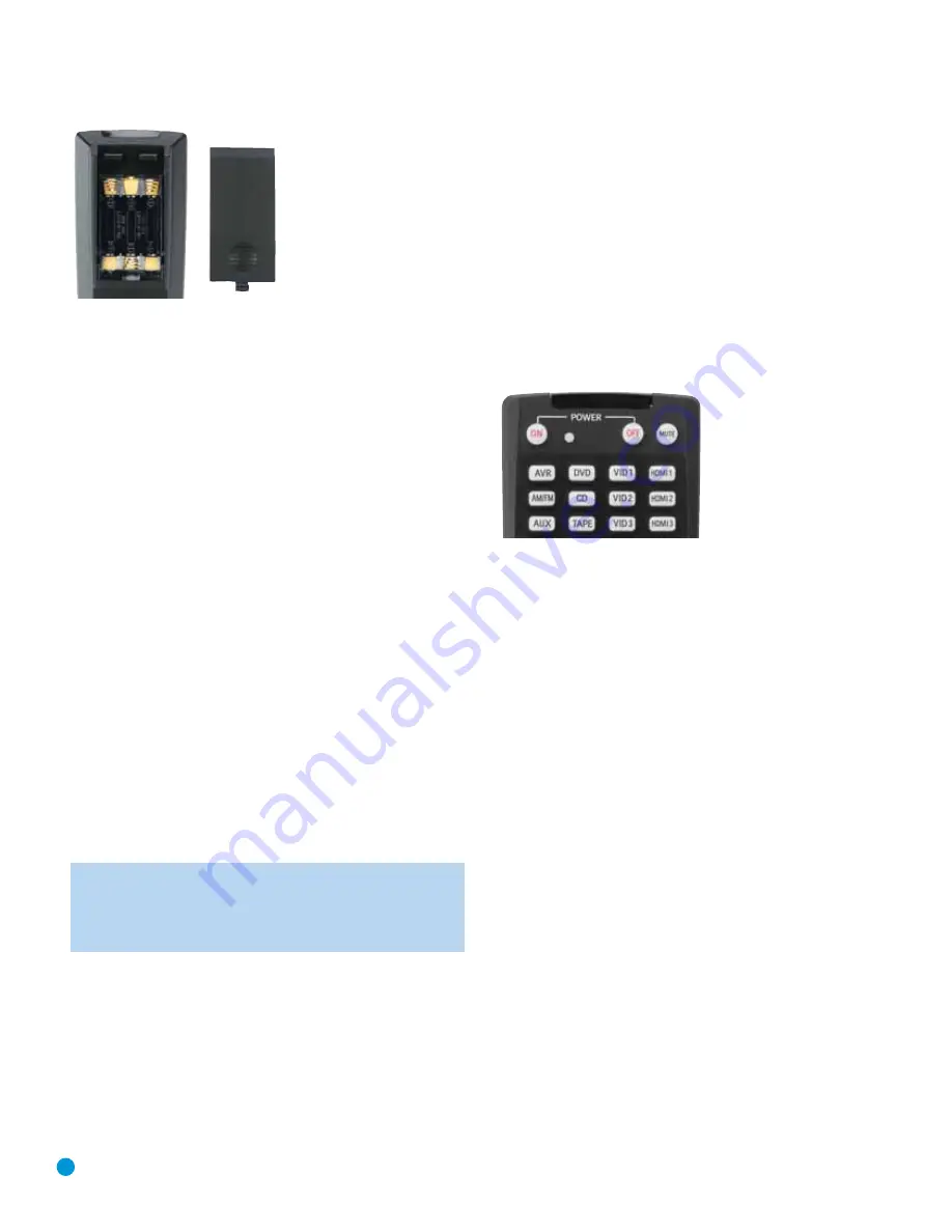
Figure 36 – Remote Control Battery Compartment

When using the remote, remember to point the lens toward the front
panel of the AVR 154. Make sure no objects, such as furniture, are
blocking the remote’s path to the receiver. Bright lights, fluorescent lights
and plasma video displays may interfere with the remote’s functioning.
The remote has a range of about 20 feet, depending on the lighting
conditions. It may be used at an angle of up to 30 degrees to either
side of the AVR.

If the remote seems to operate intermittently, or if pressing a button 
on the remote does not cause the AVR Selector or one of the Input
Selectors to light up, then make sure the batteries have been inserted
correctly, or replace all three batteries with fresh ones.

Step Eight – Program Sources Into the Remote

The AVR 154 remote not only is capable of controlling the receiver,
but it may also be programmed to control many brands and models of
VCRs, DVD players, CD players, cable boxes, satellite receivers, cassette
decks and TVs.

It may help to think of the remote as a book with pages. Each page 
represents the button functions for a different device. In order to access
the functions for a particular device, first turn to that page; that is, switch
the remote to that device mode. This is done by pressing the AVR
Button to access the codes that control the receiver, or the Input
Selector buttons to access the codes for the devices programmed 
into the remote.

The AVR 154’s remote is factory-programmed to control many 
Harman Kardon DVD and CD players.

NOTE:

The remote may be easily programmed to operate the

DMC 1000 digital media center, using the Video 1 or any of the
HDMI Input Selectors, by following the instructions below. Select
the VCR/PVR/DMC device type in number 4. Enter code 003.

If you have other source devices in your system, follow these steps to
program the correct codes into the remote.

1. Using the codes in Tables A10 – A16 of the Appendix, look up the

product type (e.g., DVD, cable TV box) and the brand name of your
source. The number(s) listed is/are potential candidates for the
correct code set for your particular device.

2. Turn on your source device.

3. This step places the remote in program mode. Refer to Figure 37.

Press and hold the Input Selector until the LED on the remote starts
to flash, then release it. When pressed, the Input Selector will light red
briefly, go dark, and then relight when the Program Indicator LED
starts to flash.

4. Program the desired device type for any of the three HDMI selectors

by pressing the corresponding Input Selector:

• Press DVD to operate a DVD player.

• Press VID1 to operate a VCR or PVR, or a Harman Kardon digital

media center.

• Press VID2 to operate a cable or satellite set-top box.

Figure 37 – Input Selectors

5. Enter a code from number 1 above.

a) If the device turns off, then press the Input Selector again to accept

the code; it will flash. The remote will exit the Program mode.

b) If the device does not turn off, try entering another code. If you 

run out of codes, you may search through all of the codes in the
remote’s library for that product type by pressing the 

or

¤

Button repeatedly until the device turns off. When the device turns
off, enter the code by pressing the Input Selector; it will flash. The
remote then exits Program mode.

6. Once you have programmed a code, try using some other functions

to control the device. Sometimes manufacturers use the same Power
code for several different models, while other codes vary. Repeat this
process until you’ve programmed a satisfactory code set that oper-
ates most of the functions you frequently use.

7. Find out which code number you have programmed by pressing 

and holding the Input Selector to enter the Program mode. Press the
OK Button, and the Program Indicator LED will flash in the code
sequence. One flash represents “1”, two flashes for “2”, and so forth.
A series of many fast flashes represents “0”. Record the codes 
programmed for each device in Table A7 in the Appendix.

If you are unable to locate a code set that correctly operates your
source device, it will not be possible to use the AVR remote to control
that device. You may still connect the source to the AVR 154 and 
operate it using the device’s original remote control.

Most of the button labels on the remote describe the button’s function
when used to control the AVR 154. However, the button may perform 
a very different function when used to control another device. Refer to

Summary of Contents for Harman/kardon AVR 154

Page 1: ...AVR 154 AUDIO VIDEO RECEIVER OWNER S MANUAL...

Page 2: ...ratus 11 Only use the attachments accessories specified by the manufacturer 12 Use only with a cart stand tripod bracket or table specified by the manufacturer or sold with the apparatus When a cart i...

Page 3: ...materials that may be damaged by heat or heavy objects Some surface finishes may be particularly sensitive to absorbing such marks due to a variety of factors beyond Harman Kardon s control including...

Page 4: ...4 STAPLE INVOICE HERE...

Page 5: ...Control 34 Mute Function 34 Tone Controls 35 Headphones 35 Source Selection 35 Audio Input Selection 35 Video Input Selection 36 6 Channel Direct Inputs 36 Using the Tuner 37 Recording 37 AUX Input 38...

Page 6: ...n com Note You ll need the product s serial number At the same time you can choose to be notified about our new products and or special promotions Audio Section 30 Watts x 5 five channels driven at fu...

Page 7: ...deo and component Digital audio one coaxial HDMI switching only Headphone Ease of Use On screen display with composite S video and component video 480i choice of blue or black background Two line dot...

Page 8: ...ear on the upper line while the surround mode is displayed on the lower line When the on screen display menu system OSD is in use the message OSD ON will appear to remind you to check the video displa...

Page 9: ...deo Inputs Video 3 Analog Audio Inputs Power Indicator Main Power Switch Standby On Switch Volume Remote IR Sensor Message Display Speaker Channel Input Indicators NOTE To make it easier to follow the...

Page 10: ...it to one of these jacks for improved audio performance Use only one type of digital audio connection for each source Coaxial Digital Audio Output If a source is also a digital audio recorder connect...

Page 11: ...eo Monitor Outputs AC Power Cord Front Speaker Outputs Surround Speaker Outputs 6 Channel Analog Audio Inputs Center Speaker Outputs Coaxial Digital Audio Output Optical Digital Audio Inputs 1 and 2 C...

Page 12: ...ne of these buttons to select a source device which is a component where a playback signal originates e g DVD CD cable TV satellite or HDTV tuner This will also turn on the receiver and switch the rem...

Page 13: ...port Controls Power Off Mute Input Selectors 6 Channel Input Selector Volume Controls TV Video Speaker Setup OK Numeric Keys Delay Memory Clear Preset Stations Selectors Disc Skip Macros Surround Mode...

Page 14: ...ptical disc changers to skip to the next disc Macros These buttons may be programmed to execute long command sequences with a single button press They are useful for programming the command to turn on...

Page 15: ...ally loud at the listening position most artists use the surround speakers for ambient effects only and they program their materials to steer very little sound to these speakers Subwoofer A subwoofer...

Page 16: ...f the wire into the hole 3 Screw the cap back into place until the wire is held snugly Figure 2 Binding Post Speaker Terminals With Bare Wires Subwoofer The subwoofer is a specialized type of loudspea...

Page 17: ...gh definition sources where the copy protected digital content is decoded inside the source These types of connections are usually used with DVD Audio SACD Blu ray Disc HD DVD and other multichannel p...

Page 18: ...video transmits the chrominance and luminance components using separate wires contained within a single cable The plug on an S video cable contains four metal pins plus a plastic guide pin Be careful...

Page 19: ...degrees from the center speaker that is slightly behind and angled toward the listener If this isn t feasible place them behind the listener with each surround speaker facing the opposite side front...

Page 20: ...t the Source Components Use the Table A5 worksheet in the Appendix to note which connections you will use for each of your source devices A source is a device where the audio and video signals origina...

Page 21: ...Selector on the remote e g DVD with the device s product code To enjoy audio from the 6 Channel Analog Audio Inputs first select the source for the video input DVD in this example and then switch the...

Page 22: ...rom a DVD use the DVD S video or composite video input and the DVD Analog Audio inputs in addition to any other connections The AVR cannot make recordings from HDMI or component video sources and digi...

Page 23: ...ct a Cable TV Satellite HDTV or Other Set Top Box for Broadcast Television NOTE If you receive your television programming using your TV with an antenna or direct cable connection connect the TV s ana...

Page 24: ...s connect the recorder s left and right analog audio outputs to the Tape Inputs on the AVR and the recorder s analog audio inputs to the AVR s Tape Outputs No video connection is required although the...

Page 25: ...utputs Composite S Video Important do not skip this step even if you have connected the AVR s HDMI or Component Video Monitor Outputs to the display To view the AVR s on screen menus and messages conn...

Page 26: ...ular device 2 Turn on your source device 3 This step places the remote in program mode Refer to Figure 37 Press and hold the Input Selector until the LED on the remote starts to flash then release it...

Page 27: ...ired the first time you turn on the AVR 154 1 Gently press the Master Power Switch until the word OFF is no longer visible The Power Indicator above the two power switches should light up in amber ind...

Page 28: ...ound Select Manual Setup and System Setup See Figure 41 NOTE Your menu s appearance may vary but the functions remain the same Figure 41 Master Menu Screen If you are an experienced home theater user...

Page 29: ...ance from each speaker to the listening position and note it in the Table A4 worksheet in the Appendix Even if all speakers are the same distance from the listening position enter the speaker distance...

Page 30: ...subwoofer NONE This setting steers all low frequency information to the front speakers and no information to the subwoofer output Use this setting with full range front speakers or with a passive or...

Page 31: ...the speaker delay settings to the factory default of 10 feet 3 0 meters at once Use the Buttons to change the setting of OFF to ON If you change any speaker s setting this line will automatically reve...

Page 32: ...r front right surround right surround left or subwoofer Figure 47 Test Tone and Channel Buttons The goal is for the sound field to sound natural with no one speaker being overly emphasized If you are...

Page 33: ...rrect source device even when you have forgotten which physical connections you used Move the cursor to the TITLE line and press the OK Button A block cur sor will blink See Figure 50 Figure 50 Retitl...

Page 34: ...1 Sleep Button When the sleep timer has been set the front panel display will automati cally dim to half brightness If you press any button on the remote or front panel the display will return to full...

Page 35: ...h to Dolby Headphone virtual surround processing indicated by the DOLBY H DH message Dolby Headphone delivers an enhanced sound field that emulates a 5 1 channel speaker system No other surround modes...

Page 36: ...materials We recommend that you connect this player as follows a Connect the player s coaxial digital audio output to the Coaxial 1 Input on the AVR This input is assigned by default to the DVD sourc...

Page 37: ...tputs Thus to make a recording you need only make sure to connect your audio or video recorder to the appropriate output jacks as described in the Installation section insert blank media and make sure...

Page 38: ...To select a surround mode using the remote control locate the button dedicated to the desired group of modes Logic 7 Dolby Sur DTS Sur DTS Neo 6 Surr DSP or Stereo Press that button repeatedly to sel...

Page 39: ...o process 2 channel audio signals to produce multichannel surround sound in a variety of modes even when no surround sound has been encoded in the recording Among the available modes are the Dolby Pro...

Page 40: ...sections of the disc such as trailers extra materials or the disc menu are only available in Dolby Digital 2 0 2 channel or PCM 2 channel mode If the main title is playing and the letters in the Spea...

Page 41: ...te distortion in some low resolution sources Default Modes During initial use or after a processor reset the AVR 154 defaults to the Logic 7 Music mode for all analog and PCM audio inputs Subsequently...

Page 42: ...s wraparound surround effect Dolby Pro Logic II Variant of Dolby Pro Logic II that emphasizes use of the surround Dolby Digital 2 0 or 2 1 Game channels and subwoofer for total immersion in the video...

Page 43: ...intelligibility Tuner PCM 32kHz 44 1kHz 48kHz 96kHz Logic 7 The AVR 154 is programmed at the factory to default to this mode for Analog 2 channel Music 2 channel signals Logic 7 Music mode is well sui...

Page 44: ...layed Dim Function Some people find the front panel messages to be distracting and would prefer to dim them or turn them off altogether When the display is dimmed or darkened it will return to full br...

Page 45: ...r program mode 2 Press the Input or AVR Selector for each device before you enter commands to be transmitted to that device This step counts as one of the 19 commands allowed for each macro 3 For the...

Page 46: ...t your local Harman Kardon service center due to internal problems No sound from surround or Incorrect surround mode Select a mode other than Stereo center speakers Input is monaural There is no surro...

Page 47: ...ital audio input HDMI 2 Input player or other audio video device HDMI capable HDMI 3 Optical 1 digital audio input if not in use HDMI 3 Input DVD player or other with Video 2 audio video device Any au...

Page 48: ...ner 6 Channel Bass Manager Global Left Right Speaker Size Small Small Small Small Small Small Small Small Small Small Small Large Center Speaker Size Small Small Small Small Small Small Small Small Sm...

Page 49: ...enter Speaker Size N A Surround Speaker Size N A Subwoofer N A Left Right Speaker Crossover N A Center Speaker Crossover N A Surround Speaker Crossover N A Subwoofer Crossover N A Left Channel Level N...

Page 50: ...e Table A7 Remote Control Codes Source Input Product Type circle one Remote Control Code Video 1 VCR PVR DMC Video 2 Cable Satellite Video 3 TV HDMI 1 DVD VCR PVR DMC Cable Satellite HDMI 2 DVD VCR PV...

Page 51: ...TV Select TV Select TV Select TV Select TV Select TV Select TV Select TV Select TV Select 15 HDMI 3 HDMI 3 Select HDMI 3 Select HDMI 3 Select HDMI 3 Select HDMI 3 Select HDMI 3 Select HDMI 3 Select HD...

Page 52: ...Mode Select Subtitle On Off CDP Select Subtitle 61 Logic 7 Logic 7 Select Back DMC1000 only 62 Stereo Stereo Mode Select Video Mode 63 Skip Down Skip DVD Step Skip Scan Thumbs Down Skip Skip DVD Skip...

Page 53: ...Brand Setup Code Number LLOYTRON 172 173 LODGENET 069 LOGIK 069 LUXMAN 128 LXI 077 154 148 MAGNAVOX 030 123 128 132 154 148 MARANTZ 115 123 148 MATSUI 148 MEMOREX 069 128 METZ 084 MGA 115 123 128 MINE...

Page 54: ...048 LLOYD 040 LXI 020 040 MAGIN 045 MAGNAVOX 040 VCR Manufacturer Brand Setup Code Number MARANTZ 018 MEMOREX 017 020 040 052 053 054 076 MGA 049 MITSUBISHI 049 131 MULTITECH 040 NAD 139 NATIONAL 140...

Page 55: ...00 112 123 131 161 162 215 PROTON 210 QUASAR 109 RADIO SHACK 126 166 213 RCA 024 081 093 150 RCX 169 CD Manufacturer Brand Setup Code Number REALISTIC 058 093 095 104 105 108 164 166 SANSUI 047 081 13...

Page 56: ...UNIDEN 323 332 348 349 350 351 354 355 381 383 389 403 466 479 480 ZENITH 384 385 387 394 419 488 TAPE Manufacturer Brand Setup Code Number HARMAN KARDON 001 CBL Manufacturer Brand Setup Code Number...

Page 57: ...IGNATURE 001 188 SPRUCER 053 081 177 189 STARCOM 002 011 163 STARGATE 120 TANDY 024 TELECAPATION 028 TEXSCAN 036 TFC 122 TIMELESS 123 TOCOM 170 205 UNITED CABLE 011 UNIVERSAL 033 034 039 042 113 VIDEO...

Page 58: ...um 5 channels driven Dimensions Product Shipping Width 17 5 16 inches 440mm 22 inches 559mm Height 6 1 2 inches 165mm 10 1 2 inches 267mm Depth 15 inches 382mm 18 3 4 inches 476mm Product Shipping Wei...

Page 59: ...59 NOTES...

Page 60: ...250 Crossways Park Drive Woodbury New York 11797 www harmankardon com 2008 Harman International Industries Incorporated All rights reserved Part No CQX1A1309Z...

Reviews: