Harman Kardon AVR35 RDS User Manual Download Page 14

Installation and Connections

System Installation

After unpacking the unit, and placing it
on a solid surface capable of supporting
its weight, you will need to make the
connections to your audio and video
equipment. These steps need to be done
only when the receiver is first installed,
or when a change is made to the input
source equipment.

Audio Equipment Connections

We recommend that you use high-quality
interconnect cables when making connec-
tions to source equipment and recorders
to preserve the quality of the signals.

When making connections to audio
source equipment or speakers it is always
a good practice to unplug the unit from
the AC wall outlet. This prevents any pos-
sibility of accidentally sending audio or
transient signals to the speakers that may
damage them.

1. Connect the analog output of a CD
player to the 

CD

inputs 

.

NOTE:

When the CD player has both

fixed and variable audio outputs it is best
to use the fixed output unless you find
that the input to the receiver is so low
that the sound is noisy, or high that the
signal is distorted.

2. Connect the Play/Out jacks of a cas-
sette deck, MD or other audio recorder to
the 

Tape Monitor In

jacks 

a

. Connect

the Record/In jacks on the recorder to
the 

Tape Monitor Out

jacks 

b

on 

the AVR35RDS.

3. Connect the output of any digital
sources to be used to the appropriate
connections on the AVR35RDS rear
panel. Note that the 

Optical

and

Coaxial

digital inputs 

‡ fl

may be

used with either a Dolby Digital (AC-3)
source or the output of a conventional
CD or LV player’s PCM (SP/DIF) output. 

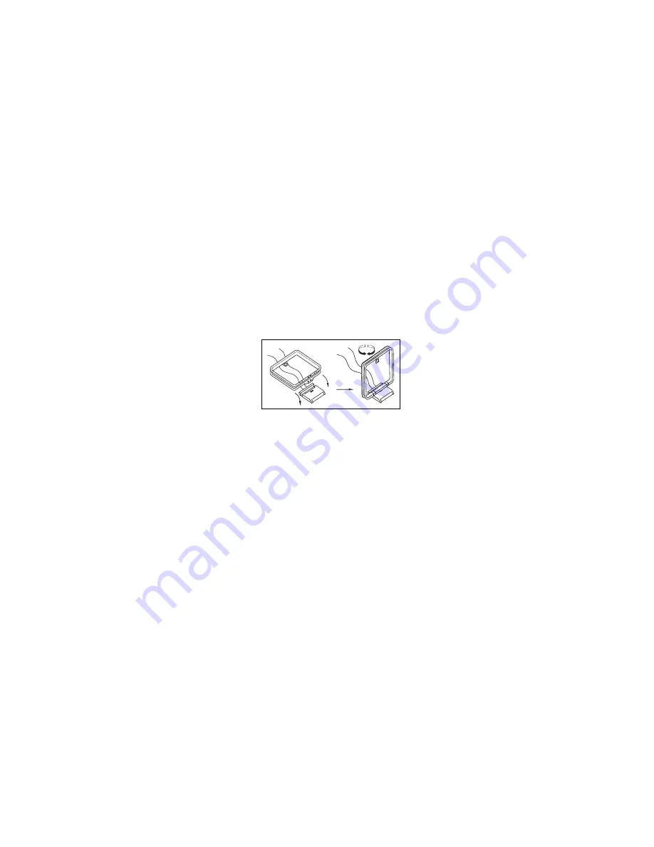
4. Assemble the AM Loop Antenna sup-
plied with the unit as shown below.
Connect it to the 

AM

and 

GND

screw

terminals 

¡

.

5. Connect an FM antenna to the 

FM (75 ohm)

connection 

. The 

FM antenna may be an external roof
antenna, an inside powered or wire lead
antenna or a connection from a cable 
TV system. Note that if the antenna or
connection uses 300-ohm twin-lead
cable, you must use the 300-ohm-to-
75-ohm adapter supplied with the unit 
to make the connection.

6. Connect the front, center and
surround speaker outputs 

• ª ‚

to the respective speakers.

To assure that all the audio signals are
carried to your speakers without loss of
clarity or resolution, we suggest that you
use high-quality speaker cable. Many
brands of cable are available, and the
choice of cable may be influenced by the
distance between your speakers and this
receiver, the type of speakers you use,
personal preferences and other factors.

Your dealer or installer is a valuable
resource to consult in selecting the
proper cable.

Regardless of the brand of cable selected,
we recommend that you use a cable con-
structed of fine, multistrand copper. Wire
of 1.5mm

2

should be used for short runs

of less than 5 meters, and wire of 2.5mm

2

or greater should be used for longer runs.

Cable with a gauge of 16 may be used for
short runs of less than ten feet. We do not
recommend that you use cables with an
AWG equivalent of 18 or higher due to
the power loss and degradation in
performance that will occur.

Cables that are run inside walls should
have the appropriate markings to indicate
listing with the appropriate testing agency
standards. Questions about running
cables inside walls should be referred to
an installer who is familiar with building
codes in your area.

When connecting wires to the speakers,
be certain to observe proper polarity.
Remember to connect the “negative” or
“black” wire to the same terminal on the
receiver and the speaker. Similarly, the
“positive” or “red” wire should be con-
nected to the like terminal on the
AVR35RDS and speaker.

We also recommend that the length of
cable used to connect speaker pairs be
identical. For example, use the same
length piece of cable to connect the front
left and front right or surround left and
surround right speakers, even if the
speakers are a different distance from
the AVR35RDS.

14

AVR35RDS 230 volt   Rev (C) 9/28/98

Summary of Contents for AVR35 RDS

Page 1: ...ve any questions about this product its installation or operation please contact your dealer They are your best local source of information Description and Features The AVR35RDS is a full featured A V receiver incorporating a wide variety of listening options In addition to Dolby Digital decoding Dolby Pro Logic and Dolby 3 Stereo are available for compati bility with the tens of thousands of movi...

Page 2: ...ntilation If this product will be installed in a cabinet or other enclosed area make certain that there is suffi cient air movement within the cabinet Under some circumstances a fan may be required Do not place the unit directly on a carpeted surface Avoid installation in extremely hot or cold locations or an area that is exposed to direct sunlight or heating equipment Avoid moist or humid locatio...

Page 3: ...splay 1 number in a square indicates a specific front panel control a number in an oval indicates a button or indicator on the remote number in a circle indicates a rear panel connection A letter in a square indicates an indicator in the front panel display 3 AVR35RDS 230 volt Rev C 9 28 98 Declaration of Conformity We Harman Kardon Europe A S Kongevejen 194B DK 3460 Birkerød DENMARK declare in ow...

Page 4: ...Test Tone Ú Surround Off Û Mute Ù Volume Control ı Delay ˆ Digital Input Selector Set Button Channel Select Speaker Select Button Selector Buttons 3 3 Information Display 3 4 Remote Sensor Window AVR 35 RDS CD T MON DVD VID 1 VID 2 VID 3 AM FM SLEEP PRESET SCAN RDS DIGITAL PRO LOGIC 3 STEREO HALL 1 HALL 2 THEATER TEST TONE SURR OFF PRESET TUNING Phones Power Mute R L Max Min Max Min Bass Treble Ba...

Page 5: ...select a source connected to these jacks press the Vid 3 Input Selector 9 Tape Selector Press this button to select the device connected to the Tape Monitor jacks a as the listening source The previously selected source will continue to show in the Information Display 3 3 and the red LED above the button will illuminate to remind you that you are listening to the tape monitor output CD Press this ...

Page 6: ...und processing and to listen to a program in tradi tional stereo from the left front and right front speakers only Û Mute Press this button to momentarily silence the speaker output of the AVR35RDS Ù Volume Control Turn the knob clockwise to increase volume counterclockwise to decrease the volume ı Delay Press this button to begin the sequence of steps required to enter delay time settings See pag...

Page 7: ...W Q P O N M V D F H I A Mute B Bypass C Analog D Dolby Digital Indicator E Optical Source F Analog Dolby Surround Mode Indicators G Coax Source H AC 3 Indicator I PCM Indicator J Analog Surround Mode Indicators K Night Indicator L Preset Number M Preset Indicator N Memory O Auto P Stereo Indicator Q Mono Indicator R Tuned Indicator S RT Indicator T CT Indicator U PTY Indicator V Main Information D...

Page 8: ...two digit display indicates the station preset number that is currently in use or that is being entered M Preset Indicator This indicator illuminates when one of the stations entered into the preset memory is tuned The number that appears below the indicator is the preset station s memory N Memory This indicator flashes when entering presets and other information into the tuner s memory O Auto Thi...

Page 9: ...utlet Power Cable Video 2 Inputs fi TV Monitor Video Output fl AC 3 PCM Coaxial Input AC 3 PCM Optical Input Remote IR In Remote IR Out a Tape Monitor In b Tape Monitor Out AM Antenna Connect the AM loop antenna supplied with the receiver to these terminals If an external AM antenna is used make connections to the AM and GND terminals in accordance with the instructions supplied with the antenna F...

Page 10: ...posite video input of a TV monitor or video projector to view the on screen menus and the output of any standard video source selected by the receiver s video switcher fl AC 3 PCM Coaxial Input Connect the coax digital output from a DVD player HDTV receiver LV player or CD player to this jack The signal may be either a Dolby Digital AC 3 signal or a standard PCM digital source AC 3 PCM Optical Inp...

Page 11: ...M2 M3 M4 AVR 35 RDS b a r s t u v w x y z c d e f g h i j k l m n o p q a Program Command Indicator b AVR Selector c Device Control Selectors d Power Button e Sleep Button f Channel Buttons g Surround Mode Selector h Buttons i Channel Button j Set Button k Night Mode l Source Selectors m 10 Button n Numeric Keys o Info Button p Clear Button q Memory Button r Tuner Mode s Direct t Enter u Preset Up...

Page 12: ...ter the button has been pressed use the buttons h to select the desired surround mode See page 24 for more information h Buttons These are multi purpose buttons They will be used most frequently to select a surround mode To change the surround mode first press the SURR button g Next press these buttons to scroll up or down through the list of surround modes that appear in the Information Display 3...

Page 13: ...ator O is NOT illuminated pressing these buttons will tune stations in single step increments See page 26 for more information w Transport Controls These con trols do not control any functions of the AVR35RDS but they are used extensively when operating a wide variety of CD players cassette decks and VCRs See page 28 for information on programming the remote to utilize these buttons x Delay Prev C...

Page 14: ... system Note that if the antenna or connection uses 300 ohm twin lead cable you must use the 300 ohm to 75 ohm adapter supplied with the unit to make the connection 6 Connect the front center and surround speaker outputs ª to the respective speakers To assure that all the audio signals are carried to your speakers without loss of clarity or resolution we suggest that you use high quality speaker c...

Page 15: ...input of your television monitor or video projector System and Power Connections The AVR35RDS is designed for flexible use with external control components and power amplifiers These connections are easy to make during an initial instal lation or at a later date should you choose to upgrade your system Remote Control Extension If the receiver is placed behind a solid or smoked glass cabinet door t...

Page 16: ...d that it takes some experimentation to find the correct location for the front speakers in your particular installation Don t be afraid to move things around until the system sounds correct Optimize your speakers so that pans across the front of the room sound smooth and that sounds from all speakers appear to arrive at the listening position at the same time with out delay from the center speake...

Page 17: ...eakers receive low frequency bass information For each of these settings use the LARGE setting if the speakers for a particular position are traditional full range loud speakers that are capable of reproducing sounds below 100Hz Use the SMALL setting for smaller frequency limited satellite speakers that do not reproduce sounds below 100Hz Note that when small speakers are used a subwoofer is requi...

Page 18: ...he Set button j again and then use the buttons h on the remote or the Selector buttons on the front panel to select the option that best describes your system based on the speaker definitions shown above When SUR SP SMALL is selected low frequency surround channel sounds will be sent to the subwoofer output only Note that if you choose this option and there is no subwoofer connected you will not h...

Page 19: ...l PRO LOGIC appears in the Main Information Display S and the PRO LOGIC indicator F lights 2 Press the Test Tone button Ò on the remote or front panel The words T T FL 0dB will appear in the Main Information Display S and the letters FL will flash once each second 3 At this point the test noise will begin to circulate among all the speakers in a clockwise rotation NOTE This is a good time to verif...

Page 20: ... twenty milliseconds The Dolby Digital mode also provides a separate setting for the center channel delay mode since the discrete nature of Dolby Digital signals makes the location of the center channel speaker more critical To calculate the delay for the center channel measure the distance from the preferred listening position in the center of the room to both the center channel speaker and eithe...

Page 21: ...d 7 Press the Set button j 8 Select the Dolby Digital mode either by pressing the front panel Dolby Digital Selector or by pressing the Surround Mode Selector g on the remote and then pressing the buttons h on the remote until DOLBY AC 3 appears in the Main Information Display S Ignore any NO DATA message that may appear 9 Press the Delay button xı on the remote or front panel The words S DELAY TI...

Page 22: ...sed remains routed to the Video Outputs 1 and TV Monitor Output fi This permits simultaneous viewing and listening to different sources During a listening session you may wish to adjust the Bass 5 and Treble 6 controls to suit your listening tastes Adjust the volume to a comfortable level using the front panel Volume Control Ù or remote Volume Up Down buttons To temporarily silence all speaker out...

Page 23: ...d in with the front left and right channels for increased realism Use this mode when you have a center channel speaker but no surround speakers Theater Surround processing uses matrix surround decoding to simulate a standard movie or stage theater These modes are designed for use with stereo recordings They provide a sound field effect that simulates the complex combination of direct and reflected...

Page 24: ...enabling true cinema reproduction in your home To utilize the Dolby Digital mode you must have a digital source properly connected to the AVR35RDS Connect the Digital datastream outputs from DVD players HDTV receivers and CD players to the AC 3 PCM Coaxial or Optical inputs on the rear panel fl In order to provide a backup signal and a source for recording the analog outputs provided on digital so...

Page 25: ...audio sources with a sampling frequency of 32kHz 44 1kHz and 48kHz Although this will enable it to decode virtually all DVD movies and HDTV sources it is possi ble that some future digital sources may not be compatible with the AVR35RDS NOTE In order to play the Dolby Digital signals that are recorded on laser discs you must have both a laser disc player with an RF output and an optional outboard ...

Page 26: ... s frequency The desired station will automatically be tuned NOTE When the FM reception of a station is weak audio quality will be increased by switching to Mono mode by pressing the Tuner Mode button r until the STEREO indicator P goes out Preset Tuning Up to 30 stations may be stored in the AVR35RDS s memory for easy recall using the front panel controls or the remote To enter a station to the m...

Page 27: ... may not choose to include some of these additional features If the data required for the selected mode is not being transmitted the Main Information Display V will show a NO NAME NO TYPE NO TEXT or NO TIME message In any FM mode the RDS function requires a strong signal for proper opera tion If you receive a partial message see blinking characters or a NO mes sage try slowly adjusting the antenna...

Page 28: ...you copy Unauthorized duplication of copyrighted materials is prohibited Output Level Trim Adjustment Normal output level adjustment for the AVR35RDS is established using the Test Tone as outlined on page 19 In some cases however it may be desirable to adjust the output levels using program material such as a test disc or a selection you are familiar with Additionally the output level for the subw...

Page 29: ...ill malfunctions a system reset may clear the problem To clear the AVR35RDS s entire system memory including tuner presets output level settings deley times and speaker configuration data first turn the unit off by pressing and releasing the Master Power Switch 1 so that it pops out from its normal recessed position Next press and hold the Sleep and the Dolby Pro Logic Ó buttons while pushing the ...

Page 30: ...ate the disk skip function on CD changers and the Numeric Keys n may operate the numeric select functions on CD players Other buttons on the remote with addi tional markings above or below the button may have these dual functions There is no harm in experimenting to see which buttons operate with your specific Harman Kardon equipment Alternate Harman Kardon CD Player Code In some cases the CD play...

Page 31: ...l desired commands have been taught from the source remote to the AVR35RDS remote press and hold the Device Control Selector c and the Set button j at the same time until the Program Command Indicator a flashes twice and then goes out and the red LED under the Device Control Selector turns off This indicates that the codes have been saved to the AVR35RDS remote s memory 7 Follow steps 1 through 6 ...

Page 32: ...he Program Command Indicator a stops flashing and turns off release the buttons All learned com mands have been erased from the AVR35RDS remote control Volume Punch Through The AVR35RDS s remote may be pro grammed to operate the Volume Control and Mute button from either the TV or the AVR to operate in conjunction with any of the eight devices controlled by the remote For example since the AVR35RD...

Page 33: ... ten macro steps available To enter the Power On Off com mand during macro programming press the Mute button DO NOT press the actual Power button Note that the Channel Up Down buttons f may NOT be used during a macro program sequence 4 When all steps up to ten have been entered press the Channel Up button f to enter the commands The red light under the Device Control Selector will blink twice and ...

Page 34: ...e Wrong device selected Remote sensor is obscured Local interference SOLUTION Make certain AC power cord is plugged into a live outlet Check to see if outlet is switch controlled Make certain that all input and speaker connections are secure Press Mute button Turn up volume control Check speaker wire connections at receiver and speaker ends for shorts Contact your local Harman Kardon service depot...

Page 35: ...no Stereo 0 3 0 5 Stereo Separation 40dB 1kHz Selectivity 400kHz 65dB Image Rejection 80dB IF Rejection 90dB Tuner Output Level 1kHz 75kHz Dev 500mV AM Tuner Section Frequency Range 531 1602kHz Signal to Noise Ratio 45dB Usable Sensitivity Loop 500µV Distortion 1kHz 50 Mod 0 8 Selectivity 10kHz 30dB Video Section Video Format PAL SECAM or NTSC Input Level Impedance 1Vp p 75 ohms Output Level Imped...

Page 36: ...Notes 36 AVR35RDS 230 volt Rev C 9 28 98 ...

Page 37: ...AVR35RDS 230 volt Rev C 9 28 98 DIGITAL COAX AC 3 AVR 35 RDS CD T MON DVD VID 1 VID 2 VID 3 AM FM SLEEP P TUNING Phones Power Printed in Korea Part 1111 AVR35RDSOM 6311 0004 010 ...

Page 38: ...VideoReceiver Owner s Manual DIGITAL COAX AC 3 SLEEP PRESET SCAN RDS DIGITAL PRO LOGIC 3 STEREO HALL 1 HALL 2 THEATER TEST TONE SURR OFF PRESET TUNING Mute R L Max Min Max Min Bass Treble Balance Volume Speaker Channel Dig Select Delay Set VIDEO 3 Video Audio R L ...

Page 39: ... Source Selection 22 Surround Mode Selection 22 24 Surround Mode Chart 23 Digital Audio Playback 24 26 Tuner Operation 26 RDS Operation 26 28 Tape Recording 28 Output Level Trim Adjustment 28 Memory Backup 29 Processor Reset 29 Programming the Remote 30 33 Pre Programmed Functions 30 Learning Commands From Another Remote 30 31 Erasing Learned Commands 31 32 Volume Punch Through 32 Macro Programmin...

Page 40: ...AVR35RDS 230 volt Rev C 9 28 98 Staple or clip original invoice here ...

Reviews: