background image

SYSTEM CONFIGURATION 

27

System Configuration

You may repeat this procedure as many times as
necessary to achieve a desired result. In order to
prevent possible damage to your hearing or your
equipment, we emphasize that you should avoid
setting the master volume above 0dB.

NOTE:

The subwoofer output is not adjusted

when the test tone is in use. To adjust the
subwoofer output you must use an external
source, following the instructions on page 36.

Manual Output Level Adjustment

Output levels may also be adjusted manually,
either to set them to a specific level with an SPL
meter, or to make fine tuning adjustments to the
levels obtained using the EzSet remote.

Manual output level adjustment is most easily
done through the 

CHANNEL ADJUST

menu (Figure 8). If you are already at the main
menu, press the 

¤

Button

D

until the on-

screen 

cursor is next to the 

CHANNEL

ADJUST

line. If you are not at the main

menu, press the 

OSD Button

v

to bring up

the 

M A S T E R M E N U

(Figure 1), and then

press the 

¤

Button

D

four times so that the

on-screen 

cursor is next to the 

CHANNEL

ADJUST

line. Press the 

Set Button

F

to

bring the 

CHANNEL ADJUST

menu

(Figure 8) to the screen.
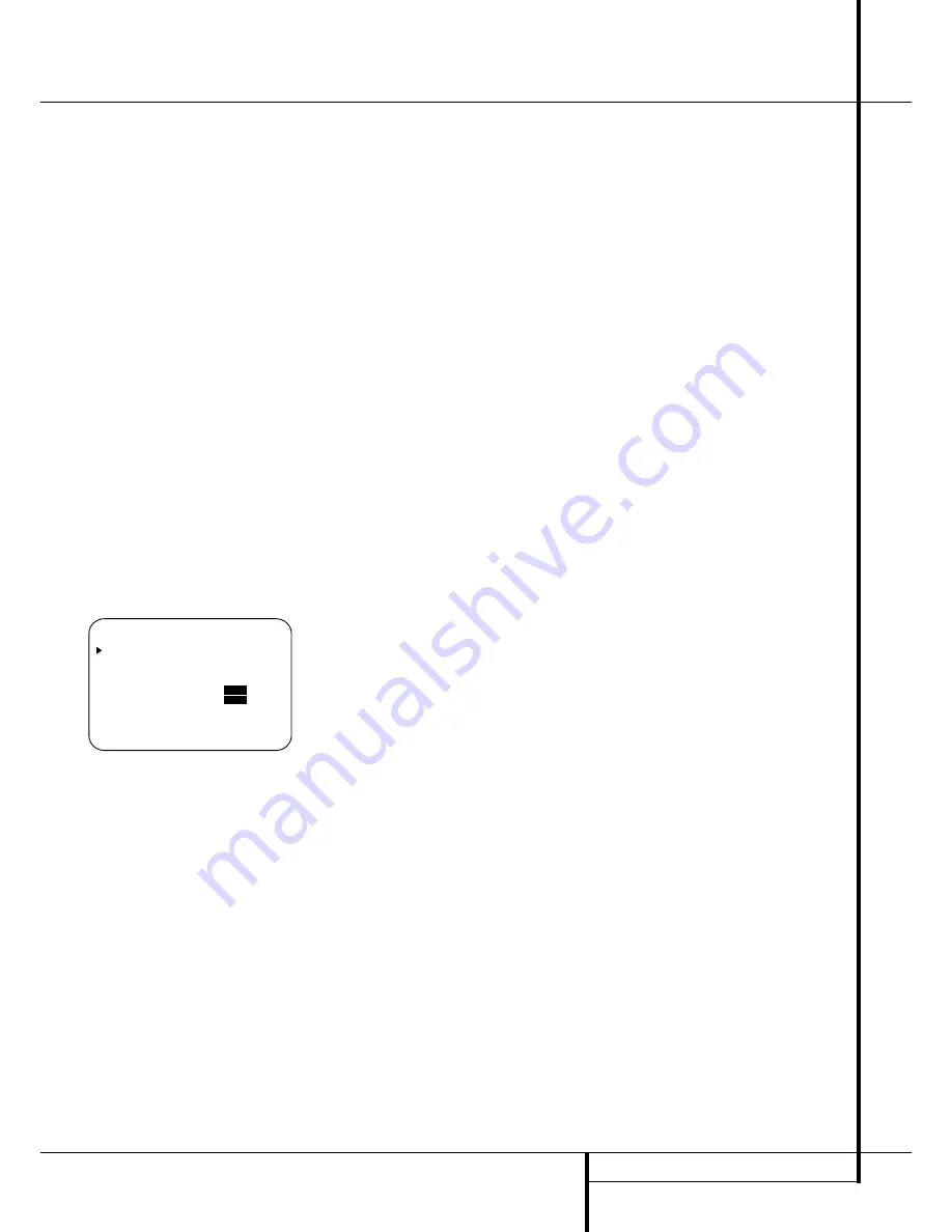
Figure 8

Once the menu appears on your video screen,
first use the 

Button

D

to move the on-

screen 

cursor so that it is next to the 

TEST

TONE

line. Press the 

/

Buttons

E&

so that 

ON

is highlighted.

You will hear a test noise circulate from speaker
to speaker in a clockwise direction around the
room. The test noise will play for two seconds in
each speaker before circulating, and a blinking
on-screen cursor will appear next to the name of
each speaker location when the sound is at that
speaker. Now turn up the volume until you can
hear the noise clearly.

IMPORTANT NOTE:

Because this test noise will

have a much lower level than normal music, the
volume must be lowered after the adjustment for
all channels is made, but BEFORE you return to
the main menu and the test tone turns off.

NOTE:

Remember to verify that the speakers

have been properly connected. As the test noise
circulates, listen to make certain that the sound
comes from the speaker position shown in the

Main Information Display

˜

. If the sound

comes from a speaker location that does NOT
match the position indicated in the display, turn
the AVR 5550 off using the 

Main Power

Switch 

1

and check the speaker wiring or

connections to external power amplifiers to make
certain that each speaker is connected to the
correct output terminal.

After checking for speaker placement, let the test
noise circulate again, and listen to see which
channels sound louder than the others. Using the
front left speaker as a reference, press the 

/

Buttons

E&

on the remote to bring all

speakers to the same volume level. When one of
the 

/

buttons is pushed, the test noise circula-

tion will pause on the channel being adjusted to
give you time to make the adjustment. When you
release the button, the circulation will resume
after five seconds. The on-screen cursor 

and the

test noise can also be moved directly to the
speaker to be adjusted by pressing the 

/

¤

buttons 

D

on the remote.

Continue to adjust the individual channels until
the volume level sounds the same from each
speaker. Note that adjustments should be made
with the 

/

Buttons

E&

on the remote

only, NOT the main volume controls.

If you are using a sound-pressure level (SPL)
meter for precise level adjustment with the test
tone, open the main 

Volume Control 

)

to -

15dB and set the individual output level for each
channel so that the meter reads 75dB,
C-Weighted Slow. After all settings are made turn
the main volume down.

You may also adjust the output levels manually
while using the level indication feature of the
EzSet remote. To activate the sensor and indica-
tor, simply press and release the 

SPL Indicator

Select Button

*

on the remote while the test

tone is circulating and set the main 

Volume

Control

)

to -15dB (respectively higher or

lower, if needed, as outlined above).
The 

Program/SPL Indicator

2

will change

color to indicate the level. Adjust the level using
the 

/

Buttons

E&

on the remote until

the LED lights green for all channels. When it is
red, the level is too high; when it is orange, the
level is too low. Press the 

SPL Indicator Select

*

button when you are finished to turn the

sensor and Indicator off.

NOTE:

The subwoofer output level is not

adjustable using the test tone. To change the
subwoofer level, follow the steps for Output
Level Trim Adjustment on page 36.

*   C H A N N E L   A D J U S T   *

F L     :   0 d B     S B R   :   0 d B          

C E N   :   0 d B     S B L   :   0 d B

F R     :   0 d B     S L     :   0 d B

S R     :   0 d B     S U B   :   0 d B

C H A N N E L   R E S E T :

O F F

  O N

T E S T   T O N E         :

O F F

  O N

B A C K   T O   M A S T E R   M E N U

Summary of Contents for AVR 5550

Page 1: ...AVR 5550 Audio VideoReceiver OWNER S MANUAL AVR 5550 ready LOGIC7 VMAx Power for the Digital Revolution ...

Page 2: ...ion Selection 40 Preset Tuning 40 RDS Operation 40 RDS Tuning 40 RDS Display Options 41 Program Search 42 Programming the Remote 42 Programming the Remote with Codes 42 Direct Code Entry 42 Auto Search Method 43 Code Readout 43 Learning Codes Table of Contents Typographical Conventions In order to help you use this manual with the remote control front panel controls and rear panel connections cert...

Page 3: ...ndling all the latest digital audio sources For compatibility with the latest HDTV video sources and progressive scan DVD players the AVR 5550 also features wide bandwidth low crosstalk component video switching Coax and optical digital outputs are available for direct connection to digital recorders and both the front panel analog audio video and coaxial digital jacks may be switched to outputs f...

Page 4: ...t proper space is provided both above and below the unit for ventilation If this product will be installed in a cabinet or other enclosed area make certain that there is sufficient air movement within the cabinet Under some circumstances a fan may be required Do not place the unit directly on a carpeted surface Avoid installation in extremely hot or cold locations or an area that is exposed to dir...

Page 5: ... Lower Display Line B press the Surround Mode Selector 9 to cycle through the individual modes available For example press this button to select Dolby modes and then press the Surround Mode Selector 9 to choose from the various mode options 6 Speaker Selector Press this button to begin the process of configuring the AVR 5550 for the type of speakers it is being used with For complete information o...

Page 6: ... the front panel Video 4 A V Ô jacks or the Coaxial 3 digital Ó jack is operating as an input When either of these jacks has been con figured for use as an output the indicator will turn red to show that the jack may be used for recording See page 21 for more information on configuring the front panel jacks as outputs rather than inputs Ó Digital Coax 3 Jack This jack is normally used for connecti...

Page 7: ...nels no speaker has been selected for that position See page 21 for more information on configuring speakers The letters inside each of the center boxes display active input channels For standard analog inputs only the L and R will light indicating a stereo input When a digital source is playing the indica tors will light to display the channels begin received at the digital input When the letters...

Page 8: ...ections to the AM and GND terminals in accordance with the instructions supplied with the antenna FM Antenna Connect the supplied indoor or an optional external FM antenna to this terminal Tape Inputs Connect these jacks to the PLAY OUT jacks of an audio recorder Tape Outputs Connect these jacks to the RECORD INPUT jacks of an audio recorder Subwoofer Output Connect this jack to the line level inp...

Page 9: ...B connection is not possible if the source out puts a separate sync signal see page 16 Remote IR Output This connection permits the IR sensor in the receiver to serve other remote controlled devices Connect this jack to the IR IN jack on Harman Kardon or other compatible equipment Remote IR Input If the AVR 5550 s front panel IR sensor is blocked due to cabinet doors or other obstructions an exter...

Page 10: ...2 connections we recommend that they be made by a trained and qualified custom installer See page 18 for more information on the RS 232 control port Fan Vents These ventilation holes are the output of the AVR 5550 s airflow system To ensure proper operation of the unit and to avoid possible damage to delicate surfaces make cer tain that these holes are not blocked and that there is at least three ...

Page 11: ... Direct Button Tuning Up Down OSD Button Dolby Mode Select Button DTS Digital Mode Selector Logic 7 Mode Select Button Transport Controls Light Button Skip Up Down Buttons Stereo Mode Select Button DTS Neo 6 Mode Select Macro Buttons RDS Selector Button Preset Up Down Clear Button Memory Button Delay Prev Ch Button Speaker Select Multiroom Volume Up Down SPL Indicator Select Learn Button Mute EzSe...

Page 12: ...Each press of the button changes the time until turn off in the following order Hold the button pressed for two seconds to turn off the Sleep mode setting Note that this button is also used to change channels on your TV VCR and Sat receiver when the appropriate source is selected using the device Input Selectors 4 A Surround Mode Selector Press this but ton to select any of the HALL THEATER or VMA...

Page 13: ...more information on storing and recalling macros RDS Select Button Press this button to dis play the various messages that are part of the RDS data system of the AVR 5550 s tuner See page 40 for more information on RDS Preset Up Down When the tuner is in use press these buttons to scroll through the stations programmed into the AVR 5550 s memory When CD or DVD is selected using the Input Selector ...

Page 14: ...ressing one of these buttons will change the input Tuning Up Down Fast Play These but tons may be used to change the frequency of the tuner These buttons may also control the Fast Play or Fast Reverse functions of compatible Harman Kardon CD DVD or cassette decks in the same room or from a remote room when an IR link is connected to the AVR 5550 ƒ Record Pause Press this button to acti vate the Re...

Page 15: ...lding codes in your area When connecting wires to the speakers be certain to observe proper polarity Note that the positive terminal of each speaker connection now carries a specific color code as noted on page 9 However most speakers will still use a red terminal for the postive connection Connect the negative or black wire to the same terminal on both the receiver and the speaker NOTE While most...

Page 16: ...di ble visible when the VCR is playing connect the Out plugs to the In jacks on the AVR and turned around If the adapter plugs are not labeled in that way pay attention to the signal flow directions as shown in the diagrams above and in the instruction attached to the adapter If uncertain don t hesitate to consult your dealer Important Notes for S Video connections 1 Only the S Video In Out of S V...

Page 17: ... cable specific control signals apart from Audio Video signals will be fed to the TV These specific signals are With all video sources the signal for automatic input selection that switches the TV automatically to the appropriate input as soon as the video source is started And with DVD players the signals automatically turning the TV to 4 3 16 9 format with 16 9 TVs or with 4 3 TVs with selectabl...

Page 18: ... a setting in the Advanced Select menu following the instructions shown on page 37 NOTE For all options you may connect an optional IR sensor Harman Kardon He1000 in the remote room to the AVR 5550 via an appro priate cable Connect the sensor s cable to the Multiroom IR Input on the AVR 5550 and use the Zone II remote to control the room vol ume Alternatively you may install an optional volume con...

Page 19: ...t of the room sound smooth When the AVR 5550 is used in 5 1 channel oper ation the preferred location for surround speak ers is on the side walls of the room at or slightly behind the listening position In a 7 1 channel system both side surround and back surround speakers are required The center of the speaker should face you see below Rear surround speakers are required when a full 7 1 channel sy...

Page 20: ...creen The Semi OSD mode uses one line displays only Note that when the full OSD system is in use the menu selections are not shown in the Infor mation Display When the full OSD menu system is used OSD ON will appear in the Upper Display Line A and the OSD Indicator C will illuminate to remind you that a video display must be used When the semi OSD system is used in conjunction with the discrete co...

Page 21: ...jack to an output press the buttons D while the IN OUT SETUP menu is on the screen so that the cursor is next to COAXIAL 3 Then press the buttons E so that the word OUT is highlighted Note that the Digital Coax 3 Status Indicator will turn red indicating that the jack is now a record output Note A signal will be sent to this jack only when the input selected for use by the AVR 5550 is dig ital Dig...

Page 22: ...those inputs where the analog bypass is desired will be routed in this fashion while other analog inputs such as a VCR or cable box will be digitized for surround processing Important Note When a speaker set with a subwoofer and two front satellites connected to the Sub s speaker outputs is used the Sub s inputs must be connected to the Front speaker outputs and LARGE must be selected for the fron...

Page 23: ...center front and surrounds by looking at the specifications page of the speaker s owner s manual by getting that infor mation from the manufacturer sWeb site or by con tacting your dealer or the manufacturer s customer service department You will need this figure to accu rately configure the next group of settings The factory default setting for all speaker positions is 100Hz If that setting is ac...

Page 24: ...operation and additional modes such as Dolby Digital EX and 7 STEREO or Logic 7 7 1 will appear as they are only available when seven main speakers are present In addition the modes DTS ES Discrete and DTS NEO 6 DTS ES Matrix available in the AVR 5550 will not appear unless a digital source is playing the correct bitstream Note When a Dolby Digital or DTS source is selected and playing the AVR 555...

Page 25: ...at first select any input associated with such a Dolby mode Next continue within the MASTER MENU Figure 1 If the system is not already at that point press the OSD button L to bring up the master menu Press the Button D three times or until the on screen cursor is pointing at the DELAYADJUST line Press the Set Button F to call up the menu Figure 7 Next move the cursor to the UNIT line and select th...

Page 26: ...d the SPL Indicator Select Button for three seconds Release it when the Program SPL Indicator 2 stops flashing and remains lit Press the 5 Button H on the remote if your system is configured for 5 1 operation with standard speakers or when it is configured for 7 1 operation but the surround back speakers are not in use with the surround mode currently selected Press the 7 Button H on the remote on...

Page 27: ...osition indicated in the display turn the AVR 5550 off using the Main Power Switch 1 and check the speaker wiring or connections to external power amplifiers to make certain that each speaker is connected to the correct output terminal After checking for speaker placement let the test noise circulate again and listen to see which channels sound louder than the others Using the front left speaker a...

Page 28: ... selected To be effective for any other mode select that mode with any input and repeat the level adjustment described above This will also allow you to com pensate level differences between speakers that may be different with each surround mode or to increase or decrease the level of certain speakers intentionally depending on the surround mode selected Note Output level adjustment is not availab...

Page 29: ...o Logic II Movie mode is optimized for movie soundtracks that are recorded with matrix surround by creating separate center rear left and rear right signals while the Pro Logic II Music mode should be used with musical selections that are recorded with matrix surround or even with normal stereo mode creating separate rear left and rear right signals in any case The Pro Logic II Emulation mode crea...

Page 30: ...center and surround positions The VMAx N or Near Field mode should be selected when your listening position is less than 1 5 m from the speakers The VMAx F or Far Field mode may be selected when your listening position is greater than 1 5 m from the speakers The VMAx modes are also available using the Headphones Output 4 When headphones are being used the Far Field mode will push the sound field a...

Page 31: ...deo game or camcorder to your home entertainment system on a temporary basis When they are configured as outputs see page 35 you can also connect an audio or video recorder composite or S Video for recording the source selected As the input source is changed the new input name will appear momentarily as an on screen display in the lower third of the video display The input name will also appear in...

Page 32: ...on page 34 To create wide enveloping sound field environ ments and defined pans and flyovers with all analog stereo recordings select the Dolby Pro Logic II Music or Emulation mode or Harman Kardon s exclusive Logic 7 Music mode for a dramatic improvement in comparison to the Dolby Pro Logic I mode of former times NOTE Once a program has been encoded with matrix surround information it retains the...

Page 33: ...check the setup menu system on your DVD player to make certain that DTS data output is enabled PCM Audio Playback PCM Pulse Code Modulation is the non com pressed digital audio system used for compact discs Non Dolby Digital DTS Laserdiscs and some special PCM encoded DVDs The digital circuits in the AVR 5550 are capable of high quality digital to analog decoding and they may be connected directly...

Page 34: ...igital source is playing the AVR 5550 senses the type of bitstream data that is present Using this information the correct surround mode will automatically be selected For example DTS bitstreams will cause the unit to switch to DTS decoding and Dolby Digital bitstreams will enable Dolby Digital decoding When the unit senses PCM data from CDs and LDs and some music DVDs or certain tracks on normal ...

Page 35: ...buttons D until the message in the lower third of the video display and the Lower Display Line B reads D RANGE OFF The Night mode may also be selected to always be on as soon as the Dolby Digital mode is activated at either level of compression using the options in the Surround Select menu See page 25 for information on using the menus to set this option IMPORTANT NOTES ON DIGITAL PLAYBACK When th...

Page 36: ...utput levels you may use the EzSet feature of the remote to guide you to the correct SPL level To use the remote for this pur pose start the test tone from the source and press and quickly release the SPL Indicator Select to activate the sensor While the test tone is played the Program SPL Indicator 2 will change color to indicate the level When it is red the level is too high when it is orange th...

Page 37: ...Indicator 3 will always remain lit to remind you that the unit is turned on If you wish to make other adjustments in the menu press the Buttons D until the on screen cursor is next to the desired setting or the BACK TO MASTER MENU line and press the Set button F If you have no other adjustments to make press the OSD Button L to exit the menu system The display brightness may also be changed by pre...

Page 38: ...en cursor is next to the ADVANCED line Press the Set Button F to enter the ADVANCED SELECT menu Figure 11 At the ADVANCED SELECT menu make certain that the on screen cursor is next to the FULL OSD TIME OUT line by pressing the Buttons D as needed Next press the buttons E until the desired time is displayed in seconds Note that unlike most of the other options in this menu this is a permanent setti...

Page 39: ...AVR Selector 5 to turn the unit on to the last source or any of the other Selector buttons to turn on to a specific source As long as an IR feed to the AVR 5550 has been established from the remote room using any of the buttons on either remote will control the remote location volume î change the tuner frequency Kè change the tuner preset or mute the output If the Remote IR Output jack on the AVR ...

Page 40: ...ed above Then 1 Press the Memory button on the remote Note that MEMORY indicator G will illuminate and flash in the Main Information Display 2 Within five seconds press the Numeric Keys H corresponding to the location where you wish to store this station s frequency Once entered the preset number will appear in the Main Information Display 3 Repeat the process after tuning any additional stations ...

Page 41: ...d Hobby JAZZ Jazz Music COUNTRY Country Music NATIONAL National Music OLDIES Oldies Music FOLK M Folk Music DOCUMENT Documentary Programs TEST Emergency Test ALARM Emergency Broadcast Information You may search for a specific Program Type PTY by following these steps 1 Press the RDS button until the current PTY is shown in the Main Information Display 2 While the PTY is shown press the Preset Up D...

Page 42: ...nd that many manufacturers use a number of different combinations of codes so it is a good idea to make certain that not only does the Power control work but that the volume channel and transport controls work as they should If functions do not work properly you may need to use a different remote code 7 If the unit does not react to any code entered if the code for your product does not appear in ...

Page 43: ... taught to all buttons on the remote The buttons with the following numbers are not learnable for numbers see drawing on page 11 4 7 8 B I O Q In these cases the Program SPL Indicator 2 keeps flashing after the button was released 5 As long as the Program SPL Indicator 2 is on steadily for five seconds press and hold the button on the original remote that you wish to teach into the AVR 5550 remote...

Page 44: ...ter commands NOTE While entering commands for Power On of any device during a macro sequence press the Mute button DO NOT press the Power ON button 3 Remember to press the appropriate Input Selector button 4 before functions are changed to another device This is also needed for the AVR Selector button 5 itself as long as it s not lit red and AVR functions shall be pro grammed 3 When all the steps ...

Page 45: ...d product type used the functions listed in the Function List tables may not correspond with the function the unit reacts on the command In these cases it s a good idea to edit the reaction of the unit into the corresponding line of the table or to set up a separate list When a button is pressed on the AVR 5550 remote the red light under the Input Selector 4 for the product being operated should f...

Page 46: ...Selector button 4 for the device that will be used to change the channels The Program SPL Indicator 2 will blink green three times and then go out to confirm the data entry Example To control the transport of a CD player while the remote is set to control the TV press the VID 2 TV Input Selector button 4 and the Mute button at the same time Next release them and press the Play button P followed by...

Page 47: ...set all commands or codes that you have entered will be erased and will need to be re entered 1 Press any of the Input Selector buttons 4 and the O button H at the same time until the Program SPL Indicator 2 begins to flash amber 2 Press the 3 button H three times 3 The red LED under the Input Selector 4 will go out and the Program SPL Indicator 2 will stop flashing and turn green 4 The Program SP...

Page 48: ... Close 30 Move Adjust Down Down 31 Delay Prev Ch Delay Adjust Return Open Close 32 1 1 1 1 33 2 2 2 2 34 3 3 3 3 35 4 4 4 4 36 5 5 5 5 37 6 6 6 6 38 7 7 7 7 39 8 8 8 8 40 Tun M Tuner Mode Chapter Repeat 41 9 9 9 9 42 0 0 0 0 43 Memory Memory Audio Time CDR Display 44 Tune Up Tune Up Next Chapter 45 Direct Direct Tuner Entry Angle Random 46 Clear Clear Clear Clear 47 Preset Up Preset Tune Up Slow F...

Page 49: ...p Up 25 Speaker Menu Menu Menu Menu Menu 26 fi Left Left Left Left 27 Set Enter Enter Enter Enter 28 fl Right Right Right Right 29 Digital Exit Exit Exit Exit Exit 30 Down Down Down Down 31 Delay Prev Ch Prev Channel Prev Channel Prev Channel 32 1 1 1 1 1 33 2 2 2 2 2 34 3 3 3 3 3 35 4 4 4 4 4 36 5 5 5 5 5 37 6 6 6 6 6 38 7 7 7 7 7 39 8 8 8 8 8 40 Tun M 41 9 9 9 9 9 42 0 0 0 0 0 43 Memory 44 Tune Up...

Page 50: ...to a live outlet Check to see if outlet is switch controlled Display lights but no sound Intermittent input connections Make certain that all input and speaker or picture connections are secure Mute is on Press Mute button Volume control is down Turn up volume control Units turns on but Front Panel Display brightness is turned off Follow the instructions in the Display Brightness section Display d...

Page 51: ...mpedance 1Vp p 75 ohms Video Frequency Response Composite and S Video 10Hz 8MHz 3dB Video Frequency Response Component 10Hz 35MHz 3dB General Power Requirement AC 220 240V 50Hz Power Consumption 120W idle 1040W maximum 7 channels driven Dimensions Max Width 440mm Height 165mm Depth 435mm Weight 20 kg Depth measurement includes knobs buttons and terminal connections Height measurement includes feet...

Page 52: ...250 Crossways Park Drive Woodbury New York 11797 www harmankardon com Harman Consumer International 2 route de Tours 72500 Château du Loir France 2003 Harman Kardon Incorporated Part No 55575890 ...

Reviews: