


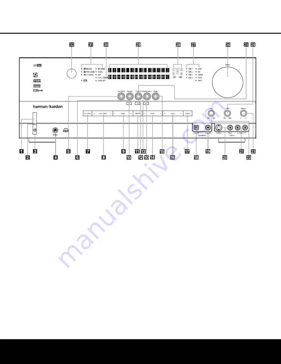
FRONT-PANEL CONTROLS
1
Main Power Switch:
Press this button to apply
power to the AVR 335. When the switch is pressed
in, the unit is in a Standby mode, as indicated by the
amber
Power Indicator
2
above the
Standby/On
Switch
3
. This button MUST be pressed in to
operate the unit. To turn the unit off and prevent the
use of the remote control, this switch should be
pressed until it pops out from the front panel and the
word “OFF” is seen at the top of the switch.
NOTE:
This switch is normally left in the “ON” position.
2
Power Indicator:
This LED lights amber when the
unit is in the Standby mode to signal that the AVR is
ready to be turned on. When the unit is in operation,
the indicator is blue.
3
Standby/On Switch:
When the
Main Power
Switch
1
is “ON,” press this button to turn on the
AVR 335; press it again to turn the unit off. The
Power
Indicator
3
turns blue when the unit is on.
4
Headphone Jack:
This jack may be used to listen
to the AVR 335’s output through a pair of headphones.
The speakers will automatically be turned off when the
headphone jack is in use. When configuring your sys-
tem using EzSet+, the calibration microphone should
be plugged into this jack using the supplied adaptor
that converts the small mini-plug at the end of the
microphone’s cord to a 1/4" plug.
5
Tone Mode:
Pressing this button enables or dis-
ables the Bass and Treble tone controls. When the but-
ton is pressed so that
TONE IN
appears in the
Lower Display Line
¯
, the
Bass
and
Treble
Ú
controls may be used to adjust the output signals.
When the button is pressed once or twice so that the
words
TONE OUT
appear in the
Lower Display
Line
¯
, the output signal will be “flat,” no matter how
the actual
Bass
and
Treble Controls
Ú
are
adjusted.
6
Speaker Select Button:
Press this button to
begin the process of configuring the unit to match the
type of speakers used in your listening room. (See
pages 22–24 for more information on speaker setup
and configuration.)
7
Surround Mode Group Selector:
Press this but-
ton to select the top-level group of surround modes.
Each press of the button will select the current or last
used mode in each of the surround mode groups
(e.g., Dolby, DTS, DTS Neo:6, Logic 7, DSP, Stereo).
When the button is pressed so that the name of the
desired surround mode group appears in the on-
screen display and in the
Lower Display Line
¯
,
press the
Surround Mode Selector
8
to cycle
through the individual modes available. For example,
press this button to select Dolby modes, and then
press the
Surround Mode Selector
8
to choose
from the various mode options.
1
Main Power Switch
2
Power Indicator
3
Standby/On Switch
4
Headphone Jack
5
Tone Mode
6
Speaker Selector
7
Surround Mode Group Selector
8
Surround Mode Selector
9
Tuning Selector
)
‹
/
›
Buttons
!
Tuner Band Selector
@
Set Button
#
Digital Input Selector
$
Preset Station Selector
%
Delay Adjust Selector
^
Input Source Selector
&
Tuner Mode Selector
*
Optical 4 Digital Input
(
Coaxial 4 Digital Input
Ó
Video 4 Video Input Jacks
Ô
Video 4 Audio Input Jacks
Bass Control
Ò
Balance Control
Ú
Treble Control
Û
Channel Adjust Selector
Ù
Volume Control
ı
Input Indicators
ˆ
Speaker/Channel Input Indicators
˜
Upper Display Line
¯
Lower Display Line
˘
Surround Mode Indicators
¸
Remote Sensor Window
FRONT-PANEL CONTROLS
FRONT-PANEL CONTROLS 5
5
NOTE:
To make it easier to follow the instructions that refer to this illustration, a larger copy may be downloaded from the Product Support section for this product at
www.harmankardon.com.


