Harman Kardon AVR 335 Owner'S Manual Download Page 31

Speaker/Channel Indicators

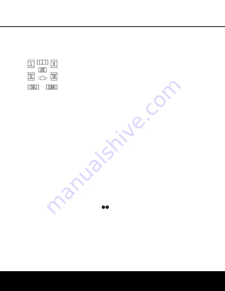
In addition to the bitstream indicators, the AVR 335
features a set of unique channel-input indicators that
tell you how many channels of digital information are
being received and/or whether the digital signal is
interrupted (see Figure 12).

Figure 12

These indicators are the L/C/R/LFE/SL/SR/SBL/SBR
letters that are inside the center boxes of the 

Speaker/

Channel Input Indicators

ˆ

on the front panel.

When a standard analog signal is in use, only the “L”
and “R” indicators will light, as analog signals have only
left and right channels.

Digital signals, however, may have two, five, six or
seven channels, depending on the program material,
the method of transmission and the way in which it
was encoded. When a digital signal is playing, the let-
ters in these indicators will light in response to the
specific signal being received. It is important to note
that although Dolby Digital, for example, is referred 
to as a “5.1” system, not all Dolby Digital DVDs or
programs are encoded for 5.1. Thus, it is sometimes
normal for a DVD with a Dolby Digital soundtrack to
trigger only the “L” and “R” indicators.

NOTE:

Many DVD discs are recorded with both “5.1”

and “2.0” versions of the same soundtrack. When
playing a DVD, always be certain to check the type of
material on the disc. Most discs show this information
in the form of a listing or icon on the back of the disc
jacket. When a disc does offer multiple soundtrack
choices, you may have to make some adjustments to
your DVD player (usually with the “Audio Select” button
or in a menu screen on the disc) to send a full 5.1
feed to the AVR 335. It is also possible for the type of 
signal feed to change during the course of a DVD
playback. In some cases, the previews of special
material will only be recorded in 2.0 audio, while the
main feature is available in 5.1 audio. The AVR 335
will automatically sense changes to the bitstream and
channel count and reflect them in these indicators.

Night Mode

A special feature of Dolby Digital is the Night mode,
which enables specially encoded Dolby Digital input
sources to be played back with full digital intelligibility
while reducing the minimum peak level by 1/4 to 1/3.
This prevents abruptly loud transitions from disturbing
others, without reducing the impact of the digital
source. The Night mode is available only when Dolby
Digital signals with special data are being played.

The Night mode may be engaged when a Dolby
Digital DVD is playing by pressing the 

Night Mode

Button

l

on the remote. Next, press the 

/

¤

Buttons

n

to select either the middle range or 

full-compression versions of the Night mode. To turn
the Night mode off, press the 

/

¤

Buttons

n

until the message in the lower third of the video dis-
play and in the 

Lower Display Line

¯

reads 

D-RANGE OFF

.

The Night mode may also be selected to always be on
at either level of compression using the options in the

DOLBY

menu. See page 19 for information on

using the menus to set this option.

IMPORTANT NOTES ON DIGITAL PLAYBACK:

• Although the AVR 335 will decode virtually all current

DVDs, CDs and HDTV sources, it is possible that some
future digital sources may not be compatible with it.

• Not all digitally encoded programs contain full 5.1-

or 6.1-channel audio. Consult the program guide
that accompanies the DVD or laser disc to deter-
mine which type of audio has been recorded on the
disc. The AVR 335 will automatically sense the digi-
tal surround encoding used and accommodate it.

• When a digital source is playing, you may not be

able to select some of the analog surround modes
such as Dolby Pro Logic II, Dolby 3, Stereo, Hall,
Theater or Logic 7.

• When a Dolby Digital or DTS source is playing,

it is not possible to make an analog recording using
the 

Tape Outputs

£

and 

Video 1 

or

Video 2

Audio Outputs

. However, the digital signals

will be passed through to the 

Digital Audio

Outputs

ab

.

PCM Audio Playback

PCM (Pulse Code Modulation) is the noncompressed
digital audio system used for compact discs and laser
discs. The digital circuits in the AVR 335 are capable of
high-quality digital-to-analog decoding, and they may
be connected directly to the digital audio output of your
CD or LD player.

Connections may be made to either the rear-panel

Optical

or 

Coaxial Inputs

dg

or the front-panel

Digital Inputs

*(

.

To listen to a PCM digital source, first select the input for
the desired source (e.g., CD). Next press the 

Digital

Select Button

#q

and then use the 

/

¤

Buttons

n

on the remote, or the

/

Selector

Buttons

)

on the front panel, until the desired choice

appears in the 

Upper Display Line 

˜

.

During PCM playback, you may select any Surround
mode except Dolby Digital or DTS.

Tuner Operation

The AVR 335’s tuner is capable of tuning AM, FM and
FM Stereo broadcast stations. Stations may be tuned
manually, or they may be stored as favorite station pre-
sets and recalled from a 30-position memory.

Station Selection

1. Press the 

AM/FM Tuner Select Button

to select the tuner as an input. The tuner may be
selected from the front panel by either pressing the

Input Source Selector

^

until the tuner is active

or by pressing the 

AM/FM Band Selector

!

.

2. Press the 

AM/FM Tuner Select Button

or 

AM/FM Band Selector

!

again to switch

between AM and FM so that the desired frequency
band is selected.

3. Press the 

Tuner Mode Button

& s

to select

manual or automatic tuning.

When the button is pressed so that 

AUTO

appears in the 

Lower Display Line

¯

each

press of the 

Tuning Selectors

9ué

will put

the tuner in a scan mode that seeks the next higher
or lower frequency station with acceptable signal
strength. An 

AUTO ST TUNED

indication 

will momentarily appear when the station stops 
at a stereo FM station, and an 

AUTO TUNED

indication will momentarily appear when an AM 
or monaural FM station is tuned. Press the Tuning 
buttons again to scan to the next receivable station.

When the button is pressed so that 

MANUAL

appears in the 

Lower Display Line

¯

each tap

of the Selector will change the frequency by one
increment. When the tuner receives a strong enough
signal for reception,

MANUAL TUNED

will

appear in the 

Lower Display Line

¯

.

4. Stations may also be tuned directly in either the

automatic or manual mode. To enter a station’s fre-
quency directly, first select the AM or FM band as
desired be pressing the 

AM/FM Tuner Select

Button

g!

. Next, press the 

Direct Button

t

. Within 5 seconds of when 

DIRECT IN

scrolls in the 

Upper Display Line

˜

, enter the

station frequency by pressing the 

Numeric Keys

r

. If you press an incorrect button while entering

33

34

35

36

37

38

39

40

41

48

49

46

47

44

45

42

43

38

39

40

41

31

32

30

28

29

25

26
27

28

29

30

24
23
22

21

20

31

37
36

35

34

33

32

31

37
36

35

34

33

32

48

49

50

51

47
46

45

44

43

42

33

34

35

36

37

38

39

40

41

48

49

46

47

44

45

42

43

38

39

40

41

31

32

30

28

29

25

26
27

28

29

30

24
23
22

21

20

31

37
36

35

34

33

32

31

37
36

35

34

33

32

48

49

50

51

47
46

45

44

43

42

OPERATION

OPERATION  31


Summary of Contents for AVR 335

Page 1: ...AVR 335 AUDIO VIDEO RECEIVER OWNER S MANUAL Power for the Digital Revolution ...

Page 2: ...gramming the Remote 37 Programming the Device Codes 37 Direct Code Entry 37 Auto Search Method 37 Code Readout 37 Macro Programming 38 Programmed Device Functions 39 Volume Punch Through 39 Channel Control Punch Through 39 Transport Control Punch Through 39 Reassigning the VID4 Device Control Selector 40 Resetting the Remote Memory 41 Function List 43 Setup Code Tables 53 Troubleshooting Guide 53 ...

Page 3: ...heater or listening room The AVR 335 includes a sophisticated multizone control system that allows you to select one source for use in the main room and a different source for audio and video distribution to a second zone with the option to assign two of the AVR 335 s output channels to the multiroom system Complete volume control in the second zone is possible with a separate infrared con trol li...

Page 4: ... and the heat generated by the amplifiers there is the remote possibility that the rubber padding on the bottom of the unit s feet may leave marks on certain wood or veneer materials Use caution when placing the unit on soft woods or other materials that may be damaged by heat or heavy objects Cleaning When the unit gets dirty wipe it with a clean soft dry cloth If necessary and only after unplugg...

Page 5: ...output signal will be flat no matter how the actual Bass and Treble Controls Ú are adjusted 6 Speaker Select Button Press this button to begin the process of configuring the unit to match the type of speakers used in your listening room See pages 22 24 for more information on speaker setup and configuration 7 Surround Mode Group Selector Press this but ton to select the top level group of surround...

Page 6: ...ther products that have a coax digital audio jack Ó Video 4 Video Input Jacks These jacks may be used for temporary connection to the composite or S video output of video games camcorders or other portable video products You may make a connection to either jack at any time but not to both simultaneously Ô Video 4 Audio Input Jacks These audio jacks may be used for temporary connection to video gam...

Page 7: ...7 44 45 42 43 38 39 40 41 31 32 30 28 29 25 26 27 28 29 30 24 23 22 21 20 31 37 36 35 34 33 32 31 37 36 35 34 33 32 48 49 50 51 47 46 45 44 43 42 33 34 35 36 37 38 39 40 41 48 49 46 47 44 45 42 43 38 39 40 41 31 32 30 28 29 25 26 27 28 29 30 24 23 22 21 20 31 37 36 35 34 33 32 31 37 36 35 34 33 32 48 49 50 51 47 46 45 44 43 42 33 34 35 36 37 38 39 40 41 48 49 46 47 44 45 42 43 38 39 40 41 31 32 30...

Page 8: ...of all devices connected to the accessory outlets should not exceed 100 watts a Optical Digital Audio Output Connect this jack to the optical digital input connector on a CD R RW MiniDisc or other digital recorder b Coaxial Digital Audio Output Connect this jack to the coaxial digital input of a CD R RW MiniDisc or other digital recorder c S Video Monitor Output When your television or other video...

Page 9: ...als in accordance with the instructions supplied with the antenna FM Antenna Jack Connect the supplied indoor or an optional external FM antenna to this terminal NOTE ON VIDEO CONNECTIONS When connecting a source device such as a VCR DVD player cable or satel lite set top box or video game to the AVR use either a composite or S video connection for each input but not both 40 41 42 43 38 39 40 41 3...

Page 10: ...ev Ch 36 Speaker Select 37 Multiroom 38 Volume Up Down 39 TV Video Selector 40 6 Channel 8 Channel Direct Input 41 Mute 43 NOTE The function names shown here are each button s feature when used with the AVR 335 Most buttons have additional functions when used with other devices See pages 41 42 for a list of these functions To make it easier to follow the instructions that refer to this illustratio...

Page 11: ... place the unit in the Sleep mode After the time shown in the display the AVR 335 will automatically go into the Standby mode Each press of the button changes the time until turn off in the following order This button is also used to change channels on your TV when the TV is selected When the AVR 335 remote is being programmed with the codes to operate another device this button is also used in th...

Page 12: ... 335 but is most often used to change to the next disc in a CD or DVD player when the remote is programmed for that type of device When the remote is used to control the AVR the VID2 TV device or the VID3 CBL SAT device these buttons are programmed to operate the DVD player s transport controls However you may use the Transport Control Punch Through feature described on page 39 to program these bu...

Page 13: ...o raise or lower the volume in that room When used in a remote room with a sensor that is connected to the Multiroom IR Input jack this button will raise or lower the volume in the remote room Play Forward Reverse Stop Buttons Press these buttons to control compatible Harman Kardon CD DVD or cassette players Mute Button When used in the room where the AVR 335 is located press this button to tempor...

Page 14: ...the connection first goes to a power ampli fier which will be connected to one or more sub woofer speakers If you are using a powered sub woofer that does not have line level input connec tions follow the instructions furnished with the speaker for connection information 9 If an external multichannel audio source with 5 1 or 7 1 channel outputs such as an external digital processor decoder DVD Aud...

Page 15: ...el should be connected to the IR IN jack on source equipment This will enable the remote room sensor to control that equipment Multiroom Connections The AVR 335 is equipped with multizone capabilities that allow it to send a separate audio source to the remote zone from the one selected for use in the main room Depending on your system s requirement three options are available for audio connection...

Page 16: ... sides of the room Speakers may be placed on a rear wall behind the listening position As with the side speakers rear surrounds should be located so that the bottom of the cabinet is at least two feet higher than the listeners ears The speakers should be no more than 6 feet behind the rear of the seating area If dipole type speakers are used on either the side or rear walls of the room please note...

Page 17: ...ou to establish different configurations for the speaker configuration digital input surround mode delay times crossover frequency and output levels for each input source This flexibility enables you to customize the way in which you listen to each source and have the AVR 335 memorize those set tings This means for example that you may use dif ferent output levels or trims for different sources or...

Page 18: ... for stereo only source material See page 29 for more informa tion on available surround modes When selecting surround modes for digital program material the AVR 335 will always examine the data stream and automatically select Dolby Digital or DTS as applicable It is easiest to complete the surround setup using the full OSD on screen menus From the MASTER MENU Figure 1 press the Buttons n until th...

Page 19: ...llowing settings as they appear in the on screen display OFF When OFF appears the Night mode will not function MID When MID appears a mild compression will be applied MAX When MAX appears a more severe compression algorithm will be applied We recommend that you select the MID setting as a starting point and change to the MAX setting later if desired The Night mode may also be adjusted directly any...

Page 20: ...noise during the process Step 2 The EzSet microphone should be placed in either your usual listening position or if there is a large seating area the center of the room at the listeners ear level You may find it convenient to use a camera tripod for stable placement of the EzSet microphone at the correct height The microphone includes a threaded insert on the bottom for tripod mounting Step 3 Plug...

Page 21: ...our system are large or small for the purpos es of bass management If desired you may use the results of the automated testing as a baseline and then make manual adjustments to the speaker size settings on a source independent basis follow ing the instructions shown on page 24 When this test is complete an output level adjustment number will be shown to the right of the SPEAKER SIZE line on the me...

Page 22: ...front channels When LARGE is selected a full range output will be sent to the front left and front right outputs Depending on the choice made in the SUBWOOFER line in this menu bass information may also be directed to the front left right speakers a subwoofer or both NOTE When the front speakers are set to the LARGE option and the surround mode is set to Surround Off or pure two channel stereo whe...

Page 23: ... frequencies under frequency selected as described below When all initial speaker size settings have been made you now have the option to take advantage of the AVR 335 s Quadruple Crossover system which allows individual crossover settings to be made for each speaker grouping The low frequency crossover point is set by the design of your speakers Depending on the design and driver complement of yo...

Page 24: ...etting for A V Sync Delay you can eliminate the loss of lip sync that may be caused by digital video applications Although EzSet calculates the delay settings for the individual speaker positions with very accurate results the setting for A V Sync Delay may only be done manually since it requires that you observe the pro gram material on your video display while adjusting the delay if any required...

Page 25: ...If you have already calibrated your system using EzSet the delay settings shown will reflect the results of the measurements made by EzSet No further changes are needed unless you wish to change a specific item to reflect your personal taste or a non standard system configuration Before beginning the output level adjustment process make certain that all speaker connections have been properly made ...

Page 26: ...channel To adjust the output level press the Buttons n until the desired level is shown in the display or on screen Once the buttons are released the test noise will begin to circulate again in 5 seconds When all channels have the same output level press the Test Button i again to complete the process If you find that the output levels are either uncomfort ably low or high you may repeat the proce...

Page 27: ...rce When a composite or S video source is selected the video signal for that input will be routed to the S Video Monitor Output c and will be viewable on a TV monitor connected to the AVR 335 6 Channel 8 Channel Direct Input There are two input choices available for use with sources such as a DVD Audio or SACD player that are connected to the 6 8 Channel Direct Inputs j Select the appropriate inpu...

Page 28: ... surround processing as these inputs take the analog output signals from an optional exter nal DVD Audio or SACD player or another source device and carry them straight through to the volume control without any further digital processing To listen to a program in traditional two channel stereo using the front left and front right speakers only plus the subwoofer if installed and configured press t...

Page 29: ...t and surround speakers to deliver a less localized soundstage that appears broader and wider than when the subwoofer is the sole source of bass energy DTS Neo 6 Cinema These two modes are available when any analog source is playing to create a six channel surround presentation from conventional Matrix encoded DTS Neo 6 Music and traditional Stereo sources Select the Cinema version of Neo 6 when a...

Page 30: ...als are present A 2 tells you that separate surround left and right signals are available This will be displayed for Dolby Digital 5 1 and DTS 5 1 programs A 1 tells you that there is only a single surround encoded surround channel This will appear for Dolby Digital bitstreams that have matrix encoding A 0 indicates that there is no surround channel information This will be displayed for two chann...

Page 31: ...corded on the disc The AVR 335 will automatically sense the digi tal surround encoding used and accommodate it When a digital source is playing you may not be able to select some of the analog surround modes such as Dolby Pro Logic II Dolby 3 Stereo Hall Theater or Logic 7 When a Dolby Digital or DTS source is playing it is not possible to make an analog recording using the Tape Outputs and Video ...

Page 32: ...o adjust the subwoofer level press the Buttons n until WOOFER LEV appears in the Lower Display Line Repeat the procedure as needed until all channels requiring adjustment have been set When all adjust ments have been made and no further adjustments are made for five seconds the AVR 335 will return to normal operation The channel output for any input may also be adjusted using the full OSD on scree...

Page 33: ...l it is changed again or until the unit is turned off If you wish to make other adjustments press the Buttons n until the on screen cursor is next to the desired setting or the BACK TO MASTER MENU line and press the Set Button p If you have no other adjustments to make press the OSD Button v to exit the menu system Turn On Volume Level As is the case with most audio video receivers when the AVR 33...

Page 34: ... Press the Set Button p to enter the ADVANCED SELECT menu Figure 13 At the ADVANCED SELECT menu Figure 13 make certain that the on screen cursor is next to the FULL OSD TIME OUT line by press ing the Buttons n as needed Next press the Buttons o until the desired time is dis played in seconds This is a permanent setting change and the Time Out entry will remain in effect until it is changed even if...

Page 35: ...ng Surround Amplifier Channel Assignment The AVR 335 is equipped with seven full power amplifier channels to allow for complete 7 1 channel operation without the need for additional external amplifiers However in some installations you may wish to use the traditional 5 1 channel configuration for the main listening room which allows the surround back left right amplifier channels to be used to pow...

Page 36: ...on or on the optional audio power amplifier connected to the Multiroom Audio Outputs Once the Multiroom system is turned on it will remain on even if the AVR 335 is placed in the Standby mode in the main room by pressing the Power Off Button a on the remote or the Standby On Button 3 on the front panel When the Multiroom system is on but the AVR is otherwise placed in Standby in the main room a MU...

Page 37: ...4 Press the Input Selector e the red light under the Input Selector will flash three times before going dark to confirm the entry 5 Try all of the functions on the remote to make cer tain that the product operates Keep in mind that many manufacturers use a number of different combinations of codes and it is a good idea to make certain that not only the power control works but also the volume chann...

Page 38: ...rticu lar button does not follow the command printed on the remote In order to see which function a button controls consult the Function List tables on pages 41 and 42 To use those tables first check the type of device being controlled e g TV VCR Next look at the remote control diagram in Figure 15 Note that each button has a number on it To find out what function a particular button has for a spe...

Page 39: ...ontrol associated with and the Mute Button at the same time until the red light appears under the Input Selector e and the Program Indicator c flashes amber 2 Press the Play Button The Program SPL Indicator c will stop flashing and stay amber 3 Press and release the Input Selector Button e for the device that will be used to change the chan nels The Program Indicator c will blink green three times...

Page 40: ...ps However once the remote is reset all commands or codes that you have entered will be erased and will need to be reentered 1 Press any of the Input Selector Buttons e and the O Button r at the same time until the Program Indicator c begins to flash amber 2 Press the 3 Button r three times 3 The red LED under the Input Selector e will go out and the Program Indicator c will stop flash ing and tur...

Page 41: ...ect Tuner Select Tuner Select Tuner Select Tuner Select Tuner Select 14 6 8 Ch Select 6 8 Ch Input Select 6 8 Ch Input Select 6 8 Ch Input Select 6 8 Ch Input Select 6 8 Ch Input Select 6 8 Ch Input Select 6 8 Ch Input Select 6 8 Ch Input Select 15 Sleep Sleep Channel Channel Channel Channel 16 Test Test Tone 17 T V TV DVD Input Select TV VCR TV Cable TV Sat TV VCR 18 Volume Up Volume Up Volume Up...

Page 42: ...4 M3 Macro 3 Macro 3 Macro 3 Macro 3 Macro 3 Macro 3 Macro 3 Macro 3 55 M4 Macro 4 Macro 4 Macro 4 Macro 4 Macro 4 Macro 4 Macro 4 Macro 4 56 Dolby Sur Dolby Mode Select 57 DTS Sur DTS Digital Modes 58 DTS Neo 6 DTS Neo 6 Select 59 Logic 7 Logic 7 Select 60 Stereo Stereo Mode Select 61 Skip Down Skip DVD Skip Skip Scan Skip DVD Skip DVD Skip DVD 62 Skip Up Skip DVD Skip Skip Scan Skip DVD Skip DVD...

Page 43: ...N 045 132 CURTIS MATHES 123 128 132 CXC 045 DAEWOO 045 087 102 105 106 108 111 114 116 119 127 128 132 DAYTRON 128 132 DIGI LINK 200 DYNASTY 045 DYNATECH 063 ELECTROHOME 115 132 EMERSON 045 123 128 132 139 157 158 159 162 205 FUNAI 045 FUTURETECH 045 GE 029 087 121 123 128 133 145 159 163 GOLD STAR LG 101 110 122 128 132 GRUNDIG 193 HALL MARK 128 HARMAN KARDON 201 HITACHI 123 128 132 144 147 INFIN...

Page 44: ...NIC 087 148 169 PHILCO 045 115 123 128 132 148 PHILIPS 033 034 035 036 123 128 132 145 148 PIONEER 024 123 128 PORTLAND 128 132 PROSCAN 133 PROTON 059 122 128 132 165 QUASAR 032 087 RADIO SHACK 045 128 132 180 196 197 RCA 021 115 123 128 133 145 161 163 REALISTIC 045 167 196 RUNCO 152 153 SAA 183 SAMPO 059 123 128 SAMSUNG 020 022 124 128 132 145 SANYO 026 054 SCOTT 045 128 132 SEARS 128 132 145 SH...

Page 45: ...rand Setup Code Number TEKNIKA 045 069 115 123 128 132 TELERENT 069 TERA 156 THOMSON 190 191 TMK 128 TOSHIBA 063 129 202 TOTEVISION 132 VIDEO CONCEPTS 160 VIDTECH 128 WARDS 069 128 132 148 YAMAHA 123 128 YORK 128 YUPITERU 045 ZENITH 069 090 ZONDA 122 ...

Page 46: ...GE 076 095 124 GO VIDEO 113 GOLD STAR LG 018 107 HARMAN KARDON 018 049 HITACHI 040 048 JC PENNEY 018 045 JENSEN 048 JVC 018 048 111 132 KENWOOD 020 048 LLOYD 040 LXI 020 040 MAGIN 045 MAGNAVOX 040 MARANTZ 018 MEMOREX 017 020 040 052 053 054 076 MGA 049 MITSUBISHI 049 131 MULTITECH 040 NAD 139 NATIONAL 140 NEC 018 048 NORDMENDE 048 OPTIMUS 159 ORION 147 PANASONIC 125 150 167 172 PHILCO 040 PHILIPS ...

Page 47: ...SCOTT 110 112 SEARS 017 020 SHARP 129 156 SONY 080 129 SOUNDESIGN 040 SYLVANIA 040 SYMPHONIC 040 TANDY 017 040 TASHICO 134 TATUNG 048 TEAC 040 048 TEKNIKA 040 THOMAS 040 TiVo 012 TMK 013 TOSHIBA 112 155 TOTEVISION 045 UNITECH 045 VECTOR RESEARCH 018 VIDEO CONCEPTS 018 040 VIDEOSONIC 045 WARDS 040 045 112 YAMAHA 018 040 048 ZENITH 040 050 076 083 ...

Page 48: ...LG 016 087 HAITAI 099 214 HARMAN KARDON 001 002 025 054 190 HITACHI 093 INKEL 216 JC PENNEY 098 147 JENSEN 153 JVC 176 195 196 KENWOOD 030 062 078 079 148 151 176 178 181 LOTTE 108 LUXMAN 077 102 LXI 164 MAGNAVOX 039 113 MARANTZ 058 084 191 192 193 MCINTOSH 194 MCS 080 098 MITSUMI 152 MODULAIRE 166 NAD 013 074 197 198 NAKAMICHI 199 200 201 NEC 069 NIKKO 053 055 ONKYO 037 038 045 046 171 175 202 20...

Page 49: ... 110 121 137 146 154 THETA DIGITAL 039 TOSHIBA 013 074 097 151 155 173 VECTOR RESEARCH 087 VICTOR 120 130 WARDS 095 YAMAHA 019 031 053 061 135 169 YORK 166 Manufacturer Brand Setup Code Number APEX DIGITAL 061 DENON 019 051 GE 003 004 GOLD STAR LG 005 HARMAN KARDON 001 JVC 006 LG 005 055 064 066 MAGNAVOX 056 MARANTZ 059 MITSUBISHI 023 NAD 062 ONKYO 009 048 PANASONIC 024 030 044 PHILIPS 056 PIONEER...

Page 50: ...366 JERROLD 454 468 484 KATHREIN 410 LEGEND 453 MACOM 317 365 369 370 371 MAGNAVOX 461 473 MEMOREX 453 NEXTWAVE 423 NORSAT 373 OPTIMUS 466 PACE DSS 487 PANASONIC 366 469 PANASONIC DBS 457 PANSAT 420 PERSONAL CABLE 418 PHILIPS 375 PICO 407 PRESIDENT 381 404 PRIMESTAR 412 454 468 475 RCA 301 439 465 490 RCA DSS 458 REALISTIC 349 480 SAMSUNG 442 SATELLITE SERVICE CO 335 388 SCIENTIFIC ATLANTA 339 SON...

Page 51: ...97 GC ELECTRONICS 113 GEMINI 032 060 GENERAL 210 GENERAL INSTRUMENT 210 GOODMIND 112 HAMLIN 056 099 100 101 117 175 208 HITACHI 001 188 JASCO 111 JERROLD 001 002 011 017 073 096 097 162 188 210 LINDSAY 118 MACOM 191 MAGNAVOX 017 019 068 MOVIE TIME 035 039 NSC 035 190 OAK 197 220 PACE 179 PANASONIC 053 176 177 189 214 PANTHER 114 PHILIPS 013 019 020 085 090 PIONEER 001 041 119 171 209 215 216 POPUL...

Page 52: ...203 221 222 SEAM 121 SIGNATURE 001 188 SPRUCER 053 081 177 189 STARCOM 002 011 163 STARGATE 120 TANDY 024 TELECAPATION 028 TEXSCAN 036 TFC 122 TIMELESS 123 TOCOM 170 205 UNITED CABLE 011 UNIVERSAL 033 034 039 042 113 VIDEOWAY 124 211 VIEWSTAR 019 025 086 089 190 ZENITH 065 125 211 219 ZENTEK 116 52 SETUP CODES ...

Page 53: ...play and digital audio stops Check that Digital Input is selected Fan does not appear to operate Additional cooling may not be required The fan is activated only when additional cooling is required due to high internal temperature It is normal for the fan to be inactive at normal volume levels In addition to the items shown above additional information on troubleshooting possible problems with you...

Page 54: ...equency Response Composite and S Video 10Hz 8MHz 3dB Video Frequency Response Component Video 10Hz 50MHz 3dB General Power Requirement AC 120V 60Hz Power Consumption 118W idle 890W maximum 7 channels driven Dimensions Product Shipping Width 17 3 inches 440mm 21 5 inches 545mm Height 6 6 inches 168mm 9 9 inches 251mm Depth 15 inches 381mm 17 9 inches 455mm Weight Product Shipping 31 lb 14 1kg 36 1 ...

Page 55: ... 8 14 15 17 28 31 Output Level Adjustments 27 32 Output Level Trim Adjustment 32 PCM 31 Polarity 14 Power Switches 5 11 13 16 17 27 Preset Stations 6 12 31 32 Processor Reset 53 Programmed Device Functions 38 39 Programming Product Codes 37 Punch Through Programming 39 Rear Panel Connections 7 9 Reassigning VID4 Device Type 39 Recalling Preset Stations 6 12 31 32 Recording 32 Remote Control Main 1...

Page 56: ... 250 Crossways Park Drive Woodbury New York 11797 www harmankardon com 2004 Harman International Industries Incorporated Part No CQX1A950Z 10 04 ...

Reviews: