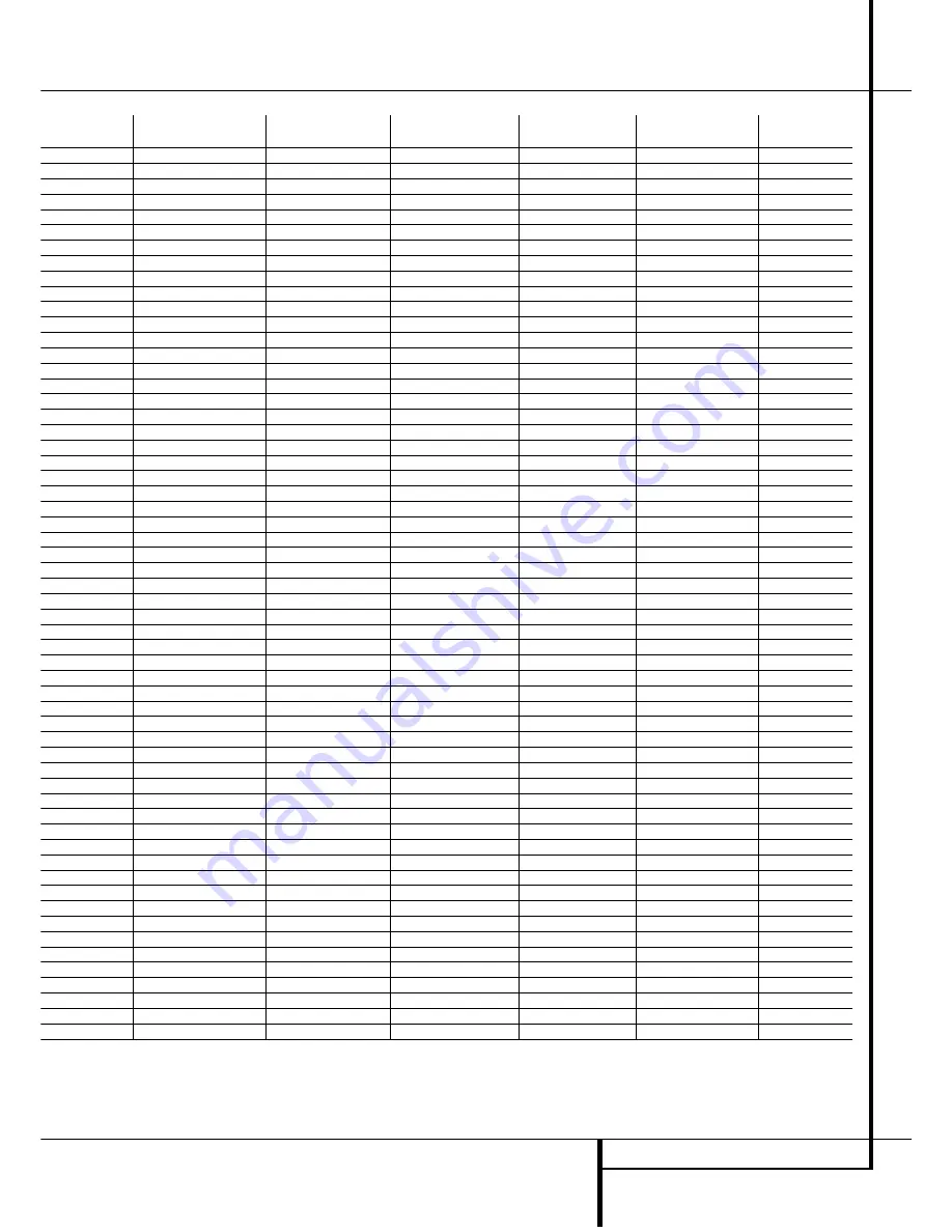
background image

FUNCTION LIST

33

Function List 

No.

Button Name

Tape

VCR (VID 1)

TV (VID 2)

CBL

SAT

1

Power On

Power On

Power On

Power On

Power On

Power On

2

Power Off

Power Off

Power Off

Power Off

Power Off

Power Off

3

Mute

Mute

4

AVR

5

DVD

6

CD

7

Tape

Tape Select

8

VID 1

VCR Select

9

VID 2

TV Select

10

CBL/SAT

CBL/SAT Select

CBL/SAT Select

11

AM/FM  

12

Sleep

C

C

C

C

13

Test  

14

TV

TV/VCR

TV/VCR

TV/Cable

TV/Sat

15

Volume Up  

Volume Up

Volume Up

16

Surround Select

Channel – 

Channel – 

Channel – 

17

Night

18

Spare

19

Volume Down

Volume Down

20

Channel/Guide

Info/Guide

Info/Guide

21

Up

Up

Up

Up

22

Speaker/Menu

Menu

Menu

Menu

Menu

23

Left

Left

Left

Left

24

Set

Enter

Enter

Enter

Enter

25

Right

Right

Right

Right

26

Digital/Exit

Exit

Exit

Exit

Exit

27

¤

Down

Down

Down

Down

28

Delay/Prev. Ch.

Prev Channel

Prev Channel

Prev Channel

29

1

1

1

1

1

30

2

2

2

2

2

31

3

3

3

3

32

4

4

4

4

33

5

5

5

5

5

34

6

6

6

6

35

7

7

7

7

7

36

8

8

8

8

8

37

Tun-M

38

9

9

9

9

9

39

0

0

0

0

0

40

Memory

41

Tune Up

42

Direct

43

Clear

Clear

Clear

Clear

Clear

44

Preset Up

45

Tune Down

46

RDS

47

Preset Down

48

M1

Cancel

Sleep

PPV

Cancel

49

M2

Fav

Fav

50

M3

Bypass

Next

51

M4

Music

Alt

52

Rewind

Rewind

Rewind

Day –

Say –

53

Play

Play

Play

54

Fast Forward

Fast Fwd

Fast Fwd

Day +

Day +

55

Record

Record/Rec.Pause

Record

56

Stop

Stop

Stop

57

Pause

Pause

58

Skip Down

Scan –

Page –

Page –

59

Skip Up

Scan + 

Page + 

Page +

Summary of Contents for AVR 2550

Page 1: ...AVR 2550 Audio VideoReceiver OWNER S MANUAL AVR 2550 AM FM RDS Power for the Digital Revolution ...

Page 2: ...ogrammed Device Function 30 Macro Programming 31 Volume Punch Through 31 Channel Control Punch Through 31 Transport Control Punch Through 31 Resetting the Remote Memory 32 Function List 34 Troubleshooting Guide 34 Processor Reset 35 Technical Specifications Table of Contents Typographical Conventions In order to help you use this manual with the remote control front panel controls and rear panel c...

Page 3: ...rround modes are available for use with sources such as CD VCR TV broadcasts and the AVR s own FM AM tuner Along with the latest Dolby ProLogicII decoding technology Dolby 3 Stereo 5 Ch Stereo and custom Hall and Theater modes only Harman Kardon receivers offer Logic 7 to create a wider more enveloping field environ ment and more defined fly overs and pans Another Harman Kardon exclusive is VMAx w...

Page 4: ...t proper space is provided both above and below the unit for ventilation If this product will be installed in a cabinet or other enclosed area make certain that there is sufficient air movement within the cabinet Under some circumstances a fan may be required Do not place the unit directly on a carpeted surface Avoid installation in extremely hot or cold locations or an area that is exposed to dir...

Page 5: ...matically be turned off when the headphones are connected 5 Selector Buttons When you are establish ing theAVR 2550 s configuration settings use these buttons to select from the choices available as shown in the Main Information Display Ú 6 Tone Mode Pressing this button enables or disables the Balance Bass and Treble tone con trols When the button is pressed so that the words TONE IN appear in th...

Page 6: ... sensor is installed Bass Control Turn this control to modify the low frequency output of the left right channels by as much as 10dB Set this control to a suitable position for your taste or room acoustics Balance Control Turn this control to change the relative volume for the front left right channels NOTE For proper operation of the surround modes this control should be at the midpoint or 12 o c...

Page 7: ... These modes include Hall 1 Hall 2 Theater and 5 Channel Stereo K Logic 7 Mode Indicators These indicators illuminate when the Logic 7 mode is in use LOGIC 7C appears for the Cinema version of Logic 7 LOGIC 7M appears for the Music version of Logic 7 See page 23 for a description of the Logic 7 Modes L Tuned Indicator This indicator illuminates when a station is being received with sufficient sig ...

Page 8: ...icators will show the minutes remaining before the AVR 2550 goes into the Standby mode See page 22 for more information on the Sleep function T Memory Indicator This indicator flashes when entering presets and other information into the tuner s memory U Stereo Indicator This indicator illuminates when an FM station is being tuned in stereo V RDS Indicator This indicator illuminates when the statio...

Page 9: ...nna is used make connections to the AM and GND terminals in accordance with the instructions supplied with the antenna 4 Video 1 Audio Outputs Connect these jacks to the RECORD INPUT audio jacks on a VCR or any other Audio recorder 5 DVD Audio Inputs Connect these jacks to the analog audio jacks on a DVD or other video source 6 FM Antenna Connect the supplied indoor or an optional external FM ante...

Page 10: ...nswitched AC Accessory Outlet This outlet may be used to power any AC device The power will remain on at this outlet regardless of whether the AVR 2550 is on or off in Standby provided that the Main Power switch 1 is on Note The total power consumption of all devices connected to the accessory outlets should not exceed 100 watts from the Unswitched Outlet F and 50 W from the Switched Outlet E G AC...

Page 11: ...n Buttons RDS Select Button Preset Up Down Clear Button Memory Button Delay Prev Ch Button Speaker Select Spare Button Volume Up Down TV Video Selector Mute NOTE The function names shown here are each button s feature when used with the AVR Most buttons have additional functions when used with other devices See page 32 for a list of these functions POWER AVR AM FM VCR ON OFF SLEEP SURR CH G U I D ...

Page 12: ...he time until turn off in the fol lowing order Hold the button pressed for two seconds to turn off the Sleep mode setting Note that this button is also used to change channels on your TV VCR and SAT receiver when selected 9 Surround Mode Selector Press this button to begin the process of changing the surround mode After the button has been pressed use the buttons C to select the desired surround m...

Page 13: ...button to enter a radio station into the AVR 2550 s preset memory After pressing the button the MEMORY indicator S will flash you then have five sec onds to enter a preset memory location using the Numeric Keys G See page 27 for more information Delay Prev Ch Press this button to begin the process for setting the delay times used by the AVR 2550 when processing surround sound After pressing this b...

Page 14: ... of 1 5 mm2 may be used for short runs of less than 4 m We do not recom mend that you use cables with an area less than 1mm2 due to the power loss and degradation in performance that will occur Cables that are run inside walls should have the appropriate markings to indicate listing with UL CSA or other appropriate testing agency stan dards Questions about running cables inside walls should be ref...

Page 15: ...VCR con nect the Out plugs to the Out jacks on the AVR Note that with some adapter types it may be just turned around If no signal is audible visi ble when the VCR is playing connect the Out plugs to the In jacks on the AVR and turned around If the adapter plugs are not labeled in that way pay attention to the signal flow direc Black Yellow Red Figure 1 SCART Cinch Adapter for playback signal flow...

Page 16: ...ot shielded even with complete surround sets only the Center speaker may be Depending on the specifics of your room acoustics and the type of speakers in use you may find that imaging is improved by moving the front left and front right speakers slightly forward of the center channel speaker If possible adjust all front loudspeakers so that they are aimed at ear height when you are seated in the l...

Page 17: ... system keeps the settings for each input sepa rate from the other inputs you will need to make these adjustments for each input used However once they are made further adjustment is only required when system components are changed To make this process as quick and as easy as possible we suggest that with each of these set tings to be made you step through each input Once you have completed the se...

Page 18: ...lector buttons 5 on the front panel to change the display to SUR SPKR 8 Press the Set button E Ó again and then use the buttons C on the remote or the Selector buttons 5 on the front panel to select the option that best describes your system based on the Surround speaker definitions shown in preceding section When SMALL is selected with all digital sur round modes low frequency surround channel so...

Page 19: ...e changed a green LED will also light next to the mode names in the Surround Mode Indicators on the front panel Note that Dolby Digital and DTS will only appear as choices when a digital input has been selected After the surround mode setting has been made with the current input repeat the setting with all inputs you will use The surround mode can also be changed at any time later and the AVR 2550...

Page 20: ...he Dolby Digital sur round mode Next press the Night button A on the remote When the button is pressed the words D R Dynamic Range followed by the current setting MID MAX OFF will appear in the Main Information Display M Press the buttons C within five seconds to select the desired setting OFF When OFF is shown in the display the Night mode will not function MID When MID is shown in the display a ...

Page 21: ...utton again to turn the test tone off and com plete the process IMPORTANT NOTE The Output level adjust ment made will be effective for the surround mode currently selected also when other inputs are selected using the same surround mode To adjust the output level with all other surround modes used step through all inputs you re using by pressing the Source Selector buttons on the front panel or th...

Page 22: ...ce Selector buttons on the remote 456 NOTE After pressing one of the Input Selector buttons 4 you must press the AVR Selector 5 to have the remote control the AVR functions The input source may also be changed by pressing the front panel Input Source Selector button Each press of the button will move the input selection through the list of available inputs As the input is changed the AVR 2550 will...

Page 23: ...not adjustable of a standard live performance theater with stereo and even pure mono sources HALL 1 The two Hall modes create sound fields that resemble a small HALL 1 or Delay time not adjustable HALL 2 medium sized HALL 2 concert hall with stereo and even pure mono sources VMAx Near When only the two front channel loudspeakers are used Harman s patented VMAx mode No surround channels VMAx Far de...

Page 24: ...ill light next to the current mode in the Surround Mode Indicators list on the front panel Regard that any time a surround mode is changed it remains associated with the input just selected until another choice is made NOTE The name of each Surround Mode will scroll through the Main Information Display M while the modes are being selected To avoid exiting from the surround mode selection process b...

Page 25: ...ill light in the Main Information Display Ú to confirm that the digital signal is Dolby Digital DTS or PCM Note that a digital input e g coaxial remains associated with any analog input e g DVD as soon as it is selected thus the digital input need not be re selected each time the appropriate input choice e g DVD is made Digital Status Indicators When a digital source is playing the AVR 2550 senses...

Page 26: ...essage in the lower third of the video display and the Main Information Display M reads D R OFF When the Night mode is active the Night Mode Indicator O will also illuminate The Night mode may also be selected to always be on at either level of compression as soon as the Dolby Digital mode is turned on using the options in the Night Mode settings See page 20 for infor mation on using this option I...

Page 27: ...t is turned off completely accidentally unplugged or subjected to a power outage This memory will last for approximately 1 week after which time all information must be reentered Tuner Operation The AVR 2550 s tuner is capable of tuning AM FM and FM Stereo broadcast stations and receiv ing RDS data Stations may be tuned manually or they may be stored as favorite station presets and recalled from a...

Page 28: ...d off try slowly adjusting the antenna or tune to another stronger RDS sta tion Program Search PTY An important feature of RDS is its capability of encoding broadcasts with Program Type PTY codes that indicate the type of material being broadcast The following list shows the abbrevia tions used to indicate each PTY along with an explanation of the PTY RDS ONLY TRAFFIC NEWS News AFFAIRS Current Aff...

Page 29: ...operly Keep in mind that many manufacturers use a number of different combinations of codes so it is a good idea to make certain that not only does the Power control work but that the volume channel and transport controls work as they should If functions do not work properly you may need to use a different remote code 7 If the unit does not react to any code en tered if the code for your product d...

Page 30: ...m with the remote but rather that no function is programmed for the button being pushed The remote was pre programmed with codes for units of the latest generation but some codes may differ from those needed for earlier units Macro Programming Macros enable you to easily repeat frequently used combinations of commands with the press of a single button on the AVR 2550 s remote control Once programm...

Page 31: ...nd press the Volume Down button followed by the VID 2 TV Input Selector button 4 NOTE To remove the Channel Control Punch Through and return the remote to its original con figuration repeat the steps shown in the example above However press the VID 1 VCR Input Selector in Steps 1 and 3 Transport Control Punch Through The AVR 2550 s remote may be programmed to operate so that the Transport Control ...

Page 32: ...st Up Up 22 Speaker Menu Speaker Adjust Menu Intro 23 fi Left 24 Set Set Enter 25 fl Right 26 Digital Exit Digital Input Select Open Close 27 Move Adjust Down Down 28 Delay Prev Ch Delay Adjust Return Open Close 29 1 1 1 1 30 2 2 2 2 31 3 3 3 3 32 4 4 4 4 33 5 5 5 5 34 6 6 6 6 35 7 7 7 7 36 8 8 8 8 37 Tun M Tuner Mode Chapter Repeat 38 9 9 9 9 39 0 0 0 0 40 Memory Memory Audio Time CDR Display 41 Tu...

Page 33: ...p Up Up 22 Speaker Menu Menu Menu Menu Menu 23 fi Left Left Left Left 24 Set Enter Enter Enter Enter 25 fl Right Right Right Right 26 Digital Exit Exit Exit Exit Exit 27 Down Down Down Down 28 Delay Prev Ch Prev Channel Prev Channel Prev Channel 29 1 1 1 1 1 30 2 2 2 2 2 31 3 3 3 3 3 32 4 4 4 4 4 33 5 5 5 5 5 34 6 6 6 6 6 35 7 7 7 7 7 36 8 8 8 8 8 37 Tun M 38 9 9 9 9 9 39 0 0 0 0 0 40 Memory 41 Tune...

Page 34: ...cord is plugged Main Power Switch 1 is pushed into a live outlet Check to see if outlet is switch controlled Display lights but no sound Intermittent input connections Make certain that all input and speaker or picture connections are secure Mute is on Press Mute button Volume control is down Turn up volume control Sound is heard but Front Panel Display brightness is turned off Follow the instruct...

Page 35: ...Signal to Noise Ratio 45dB Usable Sensitivity Loop 500µV Distortion 1kHz 50 Mod 0 8 Selectivity 9kHz 30dB Video Section Video Format PAL NTSC Input Level Impedance 1Vp p 75 ohms Output Level Impedance 1Vp p 75 ohms Video Frequency Response 10Hz 8MHz 3dB General Power Requirement AC 220 240V 50Hz Power Consumption 72W idle 580W maximum 2 channels driven Dimensions Max Width 440mm Height 166mm Depth...

Page 36: ...250 Crossways Park Drive Woodbury New York 11797 www harmankardon com Harman Consumer International 2 route de Tours 72500 Château du Loir France 2002 Harman Kardon Incorporated Part No CQX1A771Z ...

Reviews: