background image

14

INSTALLATION AND CONNECTIONS

Installation and Connections

SCART A/V Connections

For the connections described above your video
device needs RCA (cinch) connectors or/and S-
Video connectors for all Audio and Video signals:
Any normal video device (Not SVHS or High 8) for
only playback needs 3 RCA jacks, VCRs for record
and playback even 6 RCA jacks. Any S-Video
device (SVHS, High 8) needs 2 RCA (Audio) and 1
S-Video jack (Video), if it´s a playback unit, or 4
RCA (Audio In/Out) and 2 S-Video (Video In/Out)
jacks, if it´s a recording VCR.

Many european video devices are equipped with
RCA (Cinch) or S-Video jacks only partially, not
with all audio and video in/outputs needed as
described above, but with a so called Scart or
Euro-AV connector (almost rectangular jack with
21 pins, see drawings on this page).

In that case the following Scart to Cinch adapters
or cables are needed:

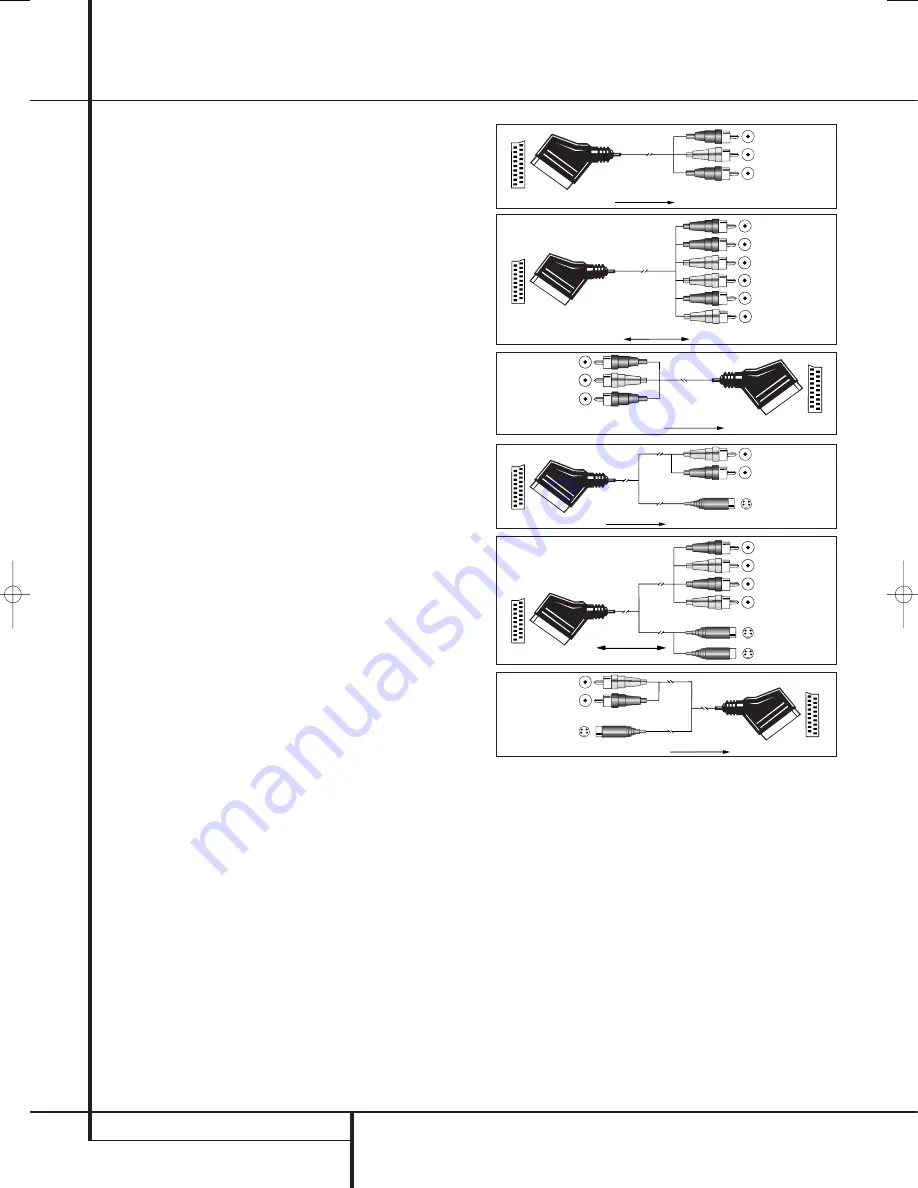
• Units for playback, such as satellite receivers,

camcorders, DVD or LD players, need an adapter
from Scart to 3 RCA plugs, see fig. 1 (normal
video devices) or from Scart to 2 RCA+1 S-
Video plugs, see fig. 4 (S-Video devices).

• HiFi VCRs need an adapter from Scart to 6 RCA

plugs, see fig. 2 (normal video), or from Scart to
4 Audio+2S-Video jacks, see fig. 5 (S-Video
VCR). Read carefully the instruction attached to
the adapter to find which of the six plugs is
used for the record signal to the VCR (connect
with the AVR´s Out jacks) and for the playback
signal from the VCR (connect with the AVR´s In
jacks). Do not misconnect Audio and Video sig-
nals. Don´t hesitate to consult your dealer, if you
are uncertain.

• If you use only normal video devices the TV

monitor needs an adapter from 3 RCA plugs to
Scart (fig. 3) only. If also S-Video devices are
used an adapter from 2 RCA+1S-Video plugs to
Scart is needed additionally (fig. 6), connected
to the SCART input on your TV that is provided
for S-Video.

Note that only the video plugs (the "yellow"
cinch plug in fig. 3 and the S-Video plug in fig. 6)
must be connected to the 

TV Monitor Output

B

, and the volume on the TV must be reduced to

minimum.

Important Note for Adapter Cables:

If the cinch connectors of the adapter you’ll use
are labeled, connect the Audio and Video ”In”
plugs with the corresponding Audio and Video
”In” jacks on the AVR (and with a VCR connect
the ”Out” plugs to the ”Out” jacks on the AVR).
Note that with some adapter types it may be just
turned around: If no signal is audible/ visible
when the VCR is playing connect the “Out” plugs
to the ”In” jacks on the AVR and turned around.
If the adapter plugs are not labeled in that way,
pay attention to the signal flow directions as

Black

Yellow

Red

Figure 1:

SCART/Cinch-Adapter for

playback;

signal flow:

SCART 

Cinch

Black

Red

Blue

Yellow

Green

White

Figure 2:

SCART/Cinch-Adapter for

record and playback;

signal flow:

SCART 

Cinch

Black

Yellow

Red

Figure 3:

Cinch/SCART-Adapter for

playback;

signal flow:

Cinch 

SCART

Rot

Schwarz

S-Video In

Figure 4:

SCART/S-Video Adapter

for playback;

signal flow:

SCART 

Cinch

Schwarz

Rot

Blau

Gelb

S-Video In

S-Video Out

Figure 5:

SCART/S-Video Adapter

for record and playback;

signal flow:

SCART 

Cinch

Rot

Schwarz

S-Video Out

Figure 6:

SCART/S-Video Adapter

for playback;

signal flow:

Cinch 

SCART

Black

Yellow

Red

Black

Red

Blue

1

Yellow

Green

1

White

Black

Yellow

Red

Red

Black

S-Video In

Red

Black

S-Video Out

Black

Red

Blue

1

Yellow

S-Video In

S-Video Out

1

Also other colours possible, e.g. brown and grey.

shown in the diagrams above and in the instruc-
tion attached to the adapter. If uncertain, don’t
hesitate to consult your dealer.

Important Notes for S-Video connections:

1. Only the S-Video In/Out of S-Video devices
must be connected to the AVR, NOT both,
normal video and S-Video In/Outputs (except the
TV, see item 2).

2. Like most common AV units the AVR does not
convert the Video signal to S-Video or vice versa.
Thus both connections must be made from the
AVR to the TV if both, Video and S-Video
sources, are used, and the appropriate input on
the TV must be selected.

Important Note for the Use of 
SCART-Cinch Adapters:

When video sources are connected to the TV
directly with a SCART cable, specific control sig-
nals apart from Audio/Video signals will be fed
to the TV. These specific signals are: With all
video sources, the signal for automatic input
selection that switches the TV automatically to
the appropriate input as soon as the video
source is started. And with DVD players, the sig-
nals automatically turning the TV to 4:3/16:9
format (with 16:9 TVs or 4:3 TVs with 16:9
capability) and turning the RGB video decoder of
the TV on or off, depending on the DVD player´s
setting. With any adapter cable, these control
signals will be lost and the appropriate setting
of the TV must be made manually.

29782_AVR132_ENG  29/11/06  12:07  Side 14

Summary of Contents for AVR 132

Page 1: ...ENGLISH AVR 132 Audio VideoReceiver OWNER S MANUAL...

Page 2: ...te 29 Programming the Remote with Codes 29 Code Readout 30 Programmed Device Functions 30 Macro Programming 31 Volume Punch Through 31 Channel Control Punch Through 31 Transport Control Punch Through...

Page 3: ...nd specific listening room environment A Stereo Direct mode bypasses the digital processor to preserve all of the subtleties of older analog two channel materials while bass management available in th...

Page 4: ...components inside this product Opening the cabinet may present a shock hazard and any modification to the prod uct will void your guarantee If water or any metal object such as a paper clip wire or a...

Page 5: ...5 Speaker Channel Input Indicators These indicators are multipurpose indicating either the speaker type selected for each channel or the incoming data signal configuration The left cen ter right right...

Page 6: ...nput sources B RDS Select Button Press this button to display the various messages that are part of the RDS data system of the AVR s tuner See page 28 for more information on RDS C Surround Mode Selec...

Page 7: ...make connections to the AM and GND terminals in accordance with the instructions supplied with the antenna 4 Video 1 Audio Outputs Connect these jacks to the RECORD INPUT audio jacks on a VCR or any...

Page 8: ...ct the Y Pr Pb component video outputs of a DVD player to these jacks Note All component inputs outputs can be used for RGB signals too in the same way as described for the Y Pr Pb signals then connec...

Page 9: ...ttons Transport Controls Skip Up Down Buttons RDS Select Button Preset Up Down Clear Button Memory Button Delay Prev Ch B Button Speaker Select Tone Mode Button Volume Up Down TV Video Selector Mute D...

Page 10: ...hat this button is also used to tune channels when the TV VCR and SAT receiver is selected using the Input Selector 4 A Night Mode Press this button to activate the Night mode This mode is available o...

Page 11: ...lence the AVR or TV set being controlled depending on which device has been selected When the AVR remote is being programmed to operate another device this button is pressed with the Input Selector bu...

Page 12: ...distance between your speakers and the receiver the type of speakers you use personal preferences and other factors Your dealer or installer is a valuable resource to consult in selecting the proper...

Page 13: ...ce may be assigned to any digital audio input on the receiver 5 Connect the Composite and S Video if S Video device is in use Monitor Output B jacks on the receiver to the composite and S Video input...

Page 14: ...a VCR connect the Out plugs to the Out jacks on the AVR Note that with some adapter types it may be just turned around If no signal is audible visible when the VCR is playing connect the Out plugs to...

Page 15: ...ear height when you are seated in the listening position Using these guidelines you ll find that it takes some experimentation to find the correct loca tion for the front speakers in your particular...

Page 16: ...elected by pressing the appropriate Input Selector on the remote control 46 The second step is to associate one of the digital inputs with the selected input source if this is needed otherwise the sel...

Page 17: ...front left right main speakers If a subwoofer is connected to the AVR you have the option to have the front left right main speakers reproduce bass frequencies at all times and have the subwoofer ope...

Page 18: ...nt speakers are band width limited satellite speakers we recom mend that you do NOT use the Bypass mode but rather use the DSP SURROUND OFF mode for stereo listening To listen to programs in the two c...

Page 19: ...et it is normal for surround speakers to operate only occasionally Artificially increasing the vol ume to the rear speakers may destroy the illu sion of an enveloping sound field that dupli cates the...

Page 20: ...evel adjust ment made will be effective for the surround mode currently selected also when other inputs are selected using the same surround mode To adjust the output level with all other surround mod...

Page 21: ...and Video Monitor Output B This permits simultaneous viewing and listening to different sources When a Video source is selected its audio signal will be fed to the speakers and the video signal for t...

Page 22: ...1 7 1 option is chosen The Logic 7 C or Cinema mode should be used with any source that contains Dolby Surround or similar matrix encoding Logic 7 C delivers increased center channel intelligibility...

Page 23: ...ts entire path of travel through the receiver to the speaker and subwoofer outputs bypassing all digital processing Digital bass management is not available in Surround Off mode The DSP Surround Off m...

Page 24: ...TS regardless of the mode that has been previously selected For more information on selecting digital sources see the following section of this manual To listen to a program in traditional two channel...

Page 25: ...ata An example of this type of display is 3 2 1 The first number indicates how many discrete front channel signals are present A 3 tells you that separate front left center and front right signals are...

Page 26: ...l mode is turned on using the options in the Night Mode settings See page 19 for infor mation on using this option IMPORTANT NOTES ON DIGITAL PLAYBACK 1 When the digital playback source is stopped or...

Page 27: ...tion presets and recalled from a 30 position memory Station Selection 1 Press the AM FM Tuner Select button 6 on the remote to select the tuner as an input The tuner may be selected from the front pan...

Page 28: ...uires a strong enough signal for proper operation Program Search PTY An important feature of RDS is its capability of encoding broadcasts with Program Type PTY codes that indicate the type of material...

Page 29: ...se a number of different combinations of codes so it is a good idea to make certain that not only does the Power control work but that the volume channel and transport controls work as they should If...

Page 30: ...erate check to see if another code set will work with more buttons Depending on the brand and product type used the functions listed in the Function List tables may not correspond with the function th...

Page 31: ...press the VID 1 VCR Input Selector button 4 and the Mute button at the same time Next release them and press the Volume Down button followed by the VID 2 TV Input Selector button 4 NOTE To remove the...

Page 32: ...peaker Adjust Menu Intro 25 A Left 26 Set Set Enter 27 B Right 28 Digital Exit Digital Input Select Open Close 29 L Move Adjust Down Down 30 Delay Prev Ch Delay Adjust Return Open Close 31 1 1 1 1 32...

Page 33: ...A Left Left Left Left 26 Set Enter Enter Enter Enter 27 B Right Right Right Right 28 Digital Exit Exit Exit Exit Exit 29 L Down Down Down Down 30 Delay Prev Ch Prev Channel Prev Channel Prev Channel...

Page 34: ...in Power Switch is pushed into a live outlet Check to see if outlet is switch controlled Display lights but no sound Intermittent input connections Make certain that all input and speaker or picture c...

Page 35: ...istortion Mono Stereo 0 15 0 3 Stereo Separation 35dB 1kHz Selectivity 400kHz 70dB Image Rejection 80dB IF Rejection 90dB AM Tuner Section Frequency Range 522 1620kHz Signal to Noise Ratio 45dB Usable...

Page 36: ...50 Crossways Park Drive Woodbury New York 11797 www harmankardon com Harman Consumer Group International 2 route de Tours 72500 Ch teau du Loir France 2006 Harman Kardon Incorporated Part No CQX1A1154...

Reviews: