background image

18

40 Rewind ™ Radial Winch

Installation and Maintenance Manual

Winch assembly

Make sure that the holes and drainage channels in the base of the winch are not obstructed
Assemble the winch in the reverse order of the sequence in the section on disassembly.

To tighten bolts, use the torque indicated in the disassembly procedure.

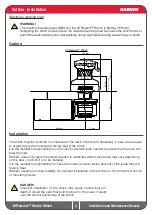
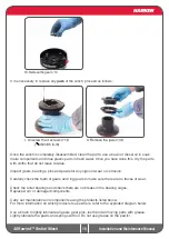
To assemble the pawls:

correctly position the spring in its housing as 
shown at left. Hold the spring closed and slide 
the pawl into its housing. Once in position, 
check that the pawls can be easily opened and 
closed with a fi nger.

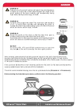
NOTICE! 

Before closing the winch, make sure the holes and 

drainage channels in the base of the winch are not obstructed.

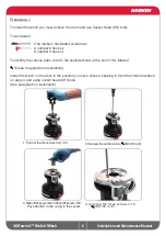
NOTICE! 

Before screw the central screw, check the correct 

position of the o-ring in the assy socket and apply Harken

®


grease.

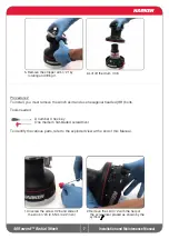
NOTICE! 

Insert the disconnect rod in the winch, with the 

groove in the lower part of the rod.

In case of doubt concerning the assembly procedure contact Harken

®

 Tech Service:  [email protected] 

OIL

THIS SIDE

DOWN

Summary of Contents for Radial 40 Rewind

Page 1: ...Radial Electric Winch 40 Rewind Installation and Maintenance Manual MRRW 03...

Page 2: ...t out 9 Positioning the self tailing arm 9 Motor installation procedure 10 Electric wiring diagrams 11 Maintenance 13 Washing 13 Maintenance table 13 Disassembly procedure 13 Exploded view with mainte...

Page 3: ...service harken it This Manual is available only in English If you do not fully understand the English language do not carry out the operations described in this Manual Technical characteristics Power...

Page 4: ...nsibility to carry out all structural tests needed to ensure that the deck can bear the load Harken does not supply the screws needed to install the winch since these may vary depending on the deck on...

Page 5: ...can weaken winch leading to failure which can cause an accident leading to severe injury or death NOTICE For winch STA STC and STCW versions only you can find the icon on the skirt to identify the dri...

Page 6: ...s refer to the exploded view at the end of this Manual Torque to apply when assembling Install the winch on the deck in the position you have chosen keeping in mind the limits described on page 4 and...

Page 7: ...r 3 hex key One medium flat bladed screwdriver To identify the various parts refer to the exploded view at the end of this Manual 1 Unscrew the screw n 26 and slide off the knob n 24 0 5 Nm 4 42 in lb...

Page 8: ...he deck in the position you have chosen keeping in mind the limits described on page 4 and using hexagonal headed bolts See paragraph on winch installation 3 Position the 5 M6 hexagonal headed bolts i...

Page 9: ...d type of the boat deck Consult the yard that built the boat in case of doubt WARNING To install the winch on the deck use only bolts in A4 stainless steel DIN 267 part11 Bolts made of other materials...

Page 10: ...e flange Motor installation procedure WARNING Make sure that the power is switched off before installing or carrying out maintenance on the winch Once you have installed the winch on the deck proceed...

Page 11: ...grams To guarantee greater efficiency in terms of safety and long life for every winch model is mandatory to install the Dual Function Control Box For more information refer to the Dual Function Contr...

Page 12: ...AWG Under5m mm2 16 4 32 8ft AWG 5m 10 m mm2 32 8 49 2ft AWG 10m 15m mm2 49 2 65 6ft AGW 15 m 20 m mm2 40 Rewind 12 V 2 32 0 50 00 70 000 95 40 Rewind 24 V 5 16 3 25 2 35 0 50 NOTICE To connect motor a...

Page 13: ...t least every 12 months After an inspection replace worn or damaged components Do not replace or modify any part of the winch with a part that is not original WARNING Periodic maintenance must be carr...

Page 14: ...Manual 9 Unscrew the 6 hex screws n 12 20Nm 177 in lb 11 Slide out the gear n 32 10 Remove drum support n 11 12 Remove pawls carrier n 33 Pay attention to the springs 7 Remove the stripper arm support...

Page 15: ...Manual 15 Pay attention to the springs and to the spacer n 6 17 Remove the command group 16 Untighten the screw n 29 18 Slide out main shaft n 30 and pay attention to the two balls n 35 14 Remove the...

Page 16: ...sion Carefully check the teeth of gears and ring gears to make sure there are no traces of wear Check the roller bearings and check there are no breaks in the bearing cages Replace worn or damaged com...

Page 17: ...nce Manual Winch exploded view with maintenance products 1Apply Harken grease on assy socket screw 2Apply Harken grease on drum gear Harken Grease G Harken Pawl Oil O Axial Threadlocker T Anti seize A...

Page 18: ...at left Hold the spring closed and slide the pawl into its housing Once in position check that the pawls can be easily opened and closed with a finger NOTICE Before closing the winch make sure the hol...

Page 19: ...inch is printed on a plate on the drum support of the winch Harken limited worldwide warranty Ordering spare parts Headquarters Harken Inc 1251 East Wisconsin Avenue Pewaukee Wisconsin 53072 3755 USA...

Page 20: ...20 40 Rewind Radial Winch Installation and Maintenance Manual Exploded view 1 2 21 19 20 25 25 38 17 14 13 12 15 11 16 21 18 39 Exploded view 40 Rewind STA STC STCW STBBB STCCC EL Winch...

Page 21: ...40 Rewind Radial Winch Installation and Maintenance Manual Exploded view 2 2 40 Rewind STA STC STCW STBBB STCCC EL Winch 38 31 17 15 5 8 4 3 7 6 32 3 4 33 30 35 34 37 22 36 29 28 27 9 10 35 23 24 26 2...

Page 22: ...per arm support 17 1 S281680097 Red line 18 4 M0601803 Screw UNI EN ISO 1207 1996 M6x35 A4 19 3 M6007103 Screw M6x50 UNI6107 20 1 S6640300A5 Cover 2 speed W40 RW Pos Q ty Code Description 21 1 1 1 1 1...

Page 23: ...r arm support 17 1 S281680097 Red line 18 4 M0601803 Screw UNI EN ISO 1207 1996 M6x35 A4 19 3 M6007103 Screw M6x50 UNI6107 20 1 S6640300A5 Cover 2 speed W40 RW Pos Q ty Code Description 21 1 1 1 1 1 2...

Page 24: ...upport 17 1 S281680097 Red line 18 4 M0601803 Screw UNI EN ISO 1207 1996 M6x35 A4 19 3 M6007103 Screw M6x50 UNI6107 20 1 S6640300A5W Cover 2 Speed W40 RW RAL 9003 Pos Q ty Code Description 21 1 1 1 1...

Page 25: ...support 17 1 S281680097 Red line 18 4 M0601803 Screw UNI EN ISO 1207 1996 M6x35 A4 19 3 M6007103 Screw M6x50 UNI6107 20 1 A76939700 Cover W40 BBB Rewind Pos Q ty Code Description 21 1 1 1 1 1 2 A7693...

Page 26: ...arm support 17 1 S281680097 Red line 18 4 M0601803 Screw UNI EN ISO 1207 1996 M6x35 A4 19 3 M6007103 Screw M6x50 UNI6107 20 1 A76939400 Cover W40 CCC Rewind Pos Q ty Code Description 21 1 1 1 1 1 2 A7...

Page 27: ...3 1 8 8 1 1 A94149500 S415360003 M6015697 M6007297 M0612097 KIT EL HO Motor Flange Horizontal Motorgear Flange Screw M6x16 UNI EN ISO 5931 2003 precote coating O Ring Seal ORM 0055 10 5 5x 1 Lip seal...

Reviews: