

EN
28
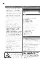
TECHNICAL DATA
Rated voltage
230 V ~ 50 Hz
Output 100 W
Max door height
2.5 m
Max door width
5 m
Max door weight
100 kg
Weight
13.5 kg
DESCRIPTION
1. Motor
2. Rail
3. Lifting arm (pre-fitted)
4. U-bracket
5. Middle roof bracket
6. Lifting arm, curved
7. Door bracket
8. Wall bracket
9. Extension to roof bracket (bend when necessary)
10. Screw M6 x 15 mm
11. Locking screw with nut M6 x 80 mm
12. Locking pin with cotter
13. Screw M8 x 20 mm with washer and nut
14. Wood screw M6 x 40
15. Sleeve/connector for motor shaft
FIG. 1
FIG. 2
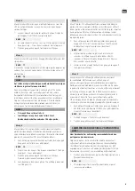
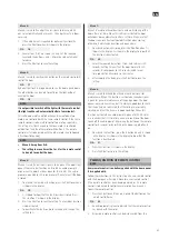
INSTALLATION
INSTALLATION INSTRUCTIONS
1. The rail is supplied complete with all parts fitted, but is
folded. Unfold the rail and put the two sliders on the rail
over the joints.
FIG. 3
2. Adjust the chain tensioner (nut on front end of rail) so that
the chain is stretched but not tight.
FIG. 4
3. Place the motor on a soft surface with the motor shaft facing
up. Put the chain drive (15) on the motor shaft and put the
rail over it, with the chain round the socket.
FIG. 5
NOTE:
Make sure the chain is fitted on the chain drive before
mounting the motor on the rail.
4. Put the 2 U-brackets over the rail, with the holes aligned to
the matching holes in the motor casing. Screw them in the
motor with the screws M6 x 15.
FIG. 6
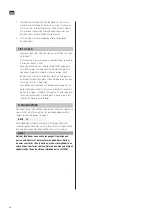
SAFETY INSTRUCTIONS
• Keep children under supervision to make sure they do not
play with the product. Keep the remote control out of the
reach of children.
• Watch the door when it moves and make sure that no
persons, animals or objects get in the way before it is fully
open or closed.
• Be careful when releasing manually – if the door is open it
could drop as a result of weak or broken springs.
• Check the installation regularly, in particular cables, springs
and brackets, for wear, damage and/or imbalance. Do not
use the product if it is damaged or incorrectly adjusted – risk
of personal injury.
• Check each month that the door changes direction if it
comes into contact with an object, 50 mm high, placed on
the floor. Adjust, if necessary, and then double-check.
• A damaged power cord must be replaced by an authorised
service centre, or other qualified personnel, to ensure safe use.
• The product is not intended to be used by persons (children
or adults) with any form of functional disorders, or by
persons who do not have sufficient experience or knowledge
on how to use it, unless they have received instructions
concerning the use of the product from someone who is
responsible for their safety.
• All surplus cables, wires and/or chains must be removed and
all equipment not needed to operate the motor must be
disabled before the drive unit is installed.
• Check before the drive unit is installed that the door is in
good mechanical condition and correctly balanced and that
it opens and closes properly.
• Mount any permanently installed controllers at least 1.5 m
above the ground and within sight of the door, but at a safe
distance from moving parts.
• Attach the warning signs highlighting the pinch risks on or
near the permanently installed controller.
• Put the warning sign for manual release near the release
device for manual release.
• Check after installation that the mechanism is adjusted
correctly and that the door changes direction if it comes into
contact with an object, 50 mm high, placed on the floor.
• Check after installation that no parts of the door extend over
public roads or footpaths.
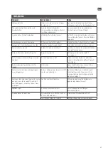
Symbol
WARNING:
Risk of getting caught.
Check regularly that the door changes
direction if it comes into contact with
an object, 50 mm high, placed on the
floor. Adjust, if necessary.
Summary of Contents for 377011
Page 5: ...1 2 1 5 2 3 6 7 8 9 4 4 4 10 5 11 6 12 7 13 8 14 9 15 ...
Page 6: ...3 4 5 15 ...
Page 7: ...7 6 8 9 8 12 10 M6 x 15 mm ...
Page 8: ...10 11 12 13 14 15 10 6 12 7 ...
Page 9: ...16 18 17 20 21 19 22 23 ...


