1 7
INSTALLATION INSTRUCTIONS CONT.
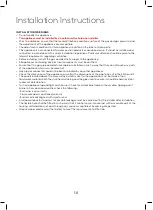
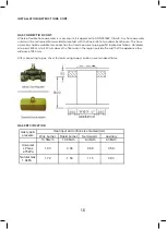
GAS ADJUSTMENT
• Take precautions on the operations and adjustments to be carried out when converting from one gas to
another.
• All work must be
carried out by a qualified technician
• Before you begin, turn off the gas and electricity supply to the appliance.
1. Change the injector of the burners
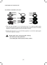
Remove the pan support, Burner lid and Flame spreader. Unscrew the injector using a 7mm box
spanner and replace it with the stipulated injector for new gas supply. Carefully reassemble the all
components. After injectors are replaced, it is advisable to strongly tighten the injector in place.
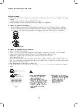
2. Adjustment of minimum level of the flame
• Turn the taps down to minimum.
• Remove the knob from the tap and place a small bladed screwdriver in the center of the tap shaft.
• The correct adjustment is obtained when the flame has a length of about 3-4mm.
- For butane / propane gas, the adjusting screw must - be tightly screwed in.
- Refit the control knob.
Make sure that the flame does not go out by quickly turning from maximum flow to minimum flow. If it
does then remove the control knob and make further adjustments to the gas flow, testing it again once
the adjustment has been made.
• Repeat this process for each one of the gas taps.
• 5 Attach the ULPG sticker to the cooker, near the gas supply inlet. Cover the Natural label that is factory
fitted.
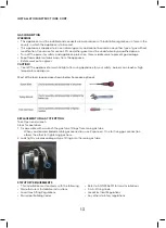
Gas adjustment
1
Injector
23
Remove the pan support, Burner lid and Flame spreader.
Unscrew the injector using a 7mm box spanner and
replace it with the stipulated injector for new gas
supply.
Carefully reassemble the all components.
After injectors are replaced, it is advisable to strongly
tighten
the injector in place.
Ŷ7DNHSUHFDXWLRQVRQWKHRSHUDWLRQVDQGDGMXVWPHQWVWREHFDUULHGRXWZKHQ
FRQYHUWLQJIURPRQHJDVWRDQRWKHU
Ŷ$OOZRUNPXVWEHFDUULHGRXWE\DTXDOL¿HGWHFKQLFLDQ
Ŷ%HIRUH\RXEHJLQWXUQRIIWKHJDVDQGHOHFWULFLW\VXSSO\WRWKHDSSOLDQFH
Change the injector of the burners.
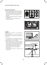
2
Control handle
Tap
Sealing ring
Adjustment of minimum level of the flame.
Turn the taps down to minimum.
-
Remove the knob from the tap and place a small
bladed screwdriver in the centre of the tap shaft.
The correct adjustment is obtained when the flame
has a length of about 3 - 4 mm.
- For butane / propane gas, the adjusting screw must
Make sure that the flame does not go out by
quickly turning from maximum flow to minimum
flow. If it does then remove the control knob and
make further adjustments to the gas flow, testing it
again once the adjustment has been made.
Repeat this process for each one of the gas taps.
be tightly screwed in.
Refit the control knob.
-
Ŷ%HIRUHSODFLQJWKHEXUQHUV
EDFNRQWKHWRSSODFHPDNHVXUH
WKDWWKHLQMHFWRULVQRWEORFNHG
FDUULHGRXWDIWHUJDVFRQYHUVLRQ
VXFKDVVRDSZDWHURUJDV
DTXDOL¿HGWHFKQLFLDQRULQVWDOOHU
KDVWRPDUN³9´RQWKHULJKWJDV
FDWHJRU\
WRPDWFKZLWKWKH
VHWWLQJLQUDWLQJSODWH
5HPRYHWKHSUHYLRXV
VHWWLQJ³9´PDUN
LQWKHHYHQWRIDPDOIXQFWLRQ
FKDQJHWKHZKROHWDS
Ŷ$IXOORSHUDWLRQDOWHVWDQGDWHVW
IRUSRVVLEOHOHDNDJHVPXVWEH
Ŷ$IWHUFRPSOHWLQJFRQYHUVLRQ
GHWHFWRU
ŶDo not dismantle the tap shaf
t
:
Attach the ULPG sticker to the cooker, near the gas
supply inlet. Cover the Natural label that is factory
fitted.
5

