background image

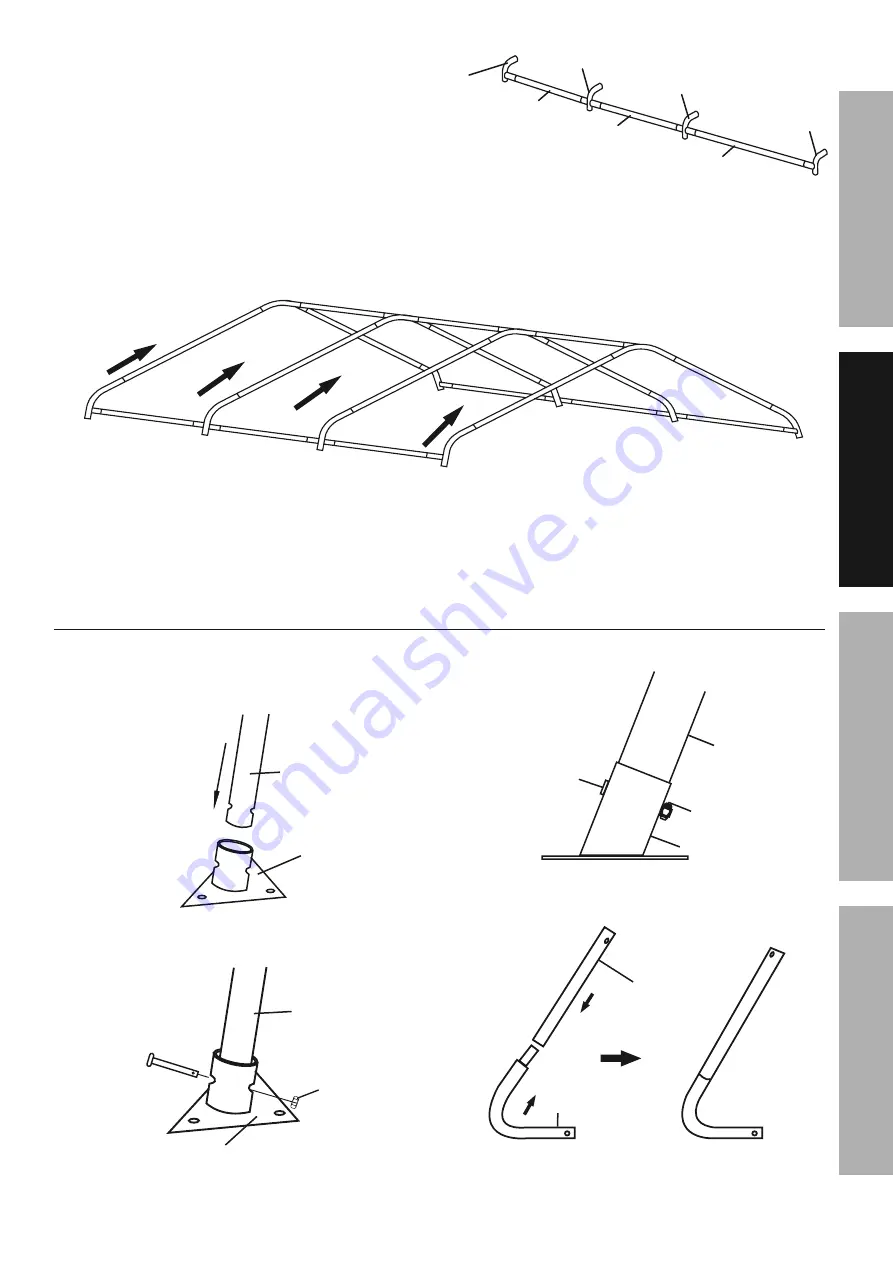
3.  Assemble a roof side rail using a 3-Way 

Side Connector B (A2), three Rails (4) with 
4-Way Side Connectors (B1) between them, 
and then a 3-Way Side Connector A (A1) 
on the other end (see Figure D).  The Rails 
connect to the straight ends of the Connectors, 
and the curved ends of all Connectors must 
face up angled the same direction, as shown.  If 
that is not the case, incorrect connectors were 
used, or they were assembled backwards.

A1

A2

4

B1

B1

4

4

Figure D:  Roof Side Rail Assembly

4.  Assemble a second identical roof side rail 

by repeating the instructions in step #3.

5.  Connect the roof side rail assemblies to the 

ends of the Rafters (3), as shown in Figure E.

A1

A2

4

B1

B1

4

4

3

3

3

3

A2

B1

B1

A1

4

Figure E:  Roof Side Rail Installation

6.  Make sure all parts assembled up to this point are 

firmly joined together.  Tap parts together gently 
with a rubber mallet (sold separately) if needed.

Stud, Foot, and Leg Assembly

1.  Assemble a Foot (7) to the bottom 

of each Center Stud (1):
a.  Place a Foot onto the bottom of the Center Stud.

7

1

b.  Align the holes and insert a Hex 

Head Bolt (12) through them.

12

9

1

14

c.  Secure with a Nut (14).

1

12

14

7

2.  Assemble a Corner Leg (6) to the bottom of 

each Corner Stud (2) as shown in Figure F.

2

6

Figure F:  Corner Leg Assembly

Page 7

For technical questions, please call 1-888-866-5797.

Item 62859 
        

S

AFETY

Op

ERA

TION

M

AINTENANCE

S

ET

up

Summary of Contents for CoverPro

Page 1: ...e receipt in a safe and dry place for future reference 19h When unpacking make sure that the product is intact and undamaged If any parts are missing or broken please call 1 888 866 5797 as soon as possible Copyright 2015 by Harbor Freight Tools All rights reserved No portion of this manual or any artwork contained herein may be reproduced in any shape or form without the express written consent o...

Page 2: ...ath or serious injury Indicates a hazardous situation which if not avoided could result in death or serious injury Indicates a hazardous situation which if not avoided could result in minor or moderate injury Addresses practices not related to personal injury Double Insulated WARNING marking concerning Risk of Eye Injury Wear ANSI approved safety goggles with side shields Read the manual before se...

Page 3: ...duct only use precautions 1 CARBON MONOXIDE HAZARD using an engine inside Shed CAN KILL YOu IN MINuTES Engine exhaust contains carbon monoxide This is a poison you cannot see or smell NEVER use an engine inside Shed EVEN IF cover is open Only use an engine OUTSIDE and far away from Shed 2 DO NOT uSE IN HIGH WIND Remove cover if harsh weather or heavy rain threatens 3 For temporary use only Do not ...

Page 4: ...ist and Diagram on page 14 TO pREVENT SERIOuS INJuRY Do not leave this product partially assembled Assemble this product completely at one time Note At least 3 workers are required for assembly Before starting assembly review the instructions and make sure there is enough time and the proper tools available to properly assemble Finger tighten all connections until assembly is done Assemble on a fl...

Page 5: ...4 5 6 A B A2 A1 B1 B1 B1 1 1 1 2 2 2 3 3 3 3 3 3 3 4 4 4 4 4 4 4 4 5 5 5 5 5 6 6 6 7 7 7 7 9 9 9 9 10 10 10 11 1 11 2 11 3 7 1 14 12 12 10 14 Page 5 For technical questions please call 1 888 866 5797 Item 62859 SAFETY OpERATION MAINTENANCE SETup ...

Page 6: ...Overview 1 Assemble ridge using three Rails 4 with 4 Way Ridge Connectors B between them and a 3 Way Ridge Connector A on each end The Rails connect to the straight ends of the Connectors and the curved free ends of the Connectors angle down as shown in Figure B A B 4 A B 4 4 Figure B Ridge Assembly 2 Connect a Rafter 3 to each free end of every Connector A B as shown in Figure C A B A B 3 3 3 3 F...

Page 7: ...he roof side rail assemblies to the ends of the Rafters 3 as shown in Figure E A1 A2 4 B1 B1 4 4 3 3 3 3 A2 B1 B1 A1 4 Figure E Roof Side Rail Installation 6 Make sure all parts assembled up to this point are firmly joined together Tap parts together gently with a rubber mallet sold separately if needed Stud Foot and Leg Assembly 1 Assemble a Foot 7 to the bottom of each Center Stud 1 a Place a Fo...

Page 8: ...est that side of the assembly on the ground and raise the other side 4 Install four Studs on the other side of the roof as explained in step 2 above A B A2 A1 B1 1 2 3 4 6 A B A2 A1 B1 B1 B1 1 1 1 2 2 2 3 3 3 3 3 3 3 4 4 4 4 4 4 4 4 6 6 6 Figure H Studs Installed on Both Sides 5 Make sure all parts assembled up to this point are firmly joined together Tap parts together gently with a rubber mallet...

Page 9: ...y not be seated together properly α α 10 2 10 2 Figure I Verify and Adjust Frame Measurements 4 Once the frame is positioned leveled and squared anchor the four Corner Legs 6 as follows a Thread the Anchor 11 1 into the ground near the Corner Leg until the top of the Anchor only extends about 3 above the ground Note Verify that there are no utility lines nearby before driving anchors If there are ...

Page 10: ... Inserting Hook into Corner Leg 3 Lift and lower the Ratchet s handle to wind and tighten the strap onto the spindle Figure M Tightening Ratchet NOTICE Excessive tightening will damage straps Covers and Corner Legs Releasing Ratchet Tie Downs 1 Depress the spring loaded bar on the handle 2 Open Ratchet handle completely 3 Unwind the strap Figure N Releasing Ratchet Page 10 For technical questions ...

Page 11: ...UBING INTO THE HEM ON THE COVER FLAPS 4 place strap and flaps inside frame 3 A 4 Figure O Door Cover Installation 3 Reconnect the Rail securely to the 3 Way Ridge Connector 4 Repeat step 2 for the 3 Way Side Connectors A B A1 A2 so that the Door Cover looks as shown in Figure O and Figure P Zipper Figure p Wrap Around Side Connectors 5 Use Ratchet Tie Downs 8 to attach the Cover to the Corner Legs...

Page 12: ...become twisted Fabric Tubes Figure S pull Roof Cover Over Frame using Straps 4 Insert the Bottom Rails 5 into the fabric tubes on each side of the Roof Cover 15 5 Figure T Insert Bottom Rails 5 Make sure the Bottom Rails are level and horizontal Bottom Rails 5 Figure u Bottom Rails in place 6 Attach the Bottom Rails to the Corner Studs 2 using 3 Way End Rail Clamps 9 Bolts and Nuts 13 14 and to th...

Page 13: ...DISTRIBUTOR HAS PROVIDED THE PARTS LIST AND ASSEMBLY DIAGRAM IN THIS MANUAL AS A REFERENCE TOOL ONLY NEITHER THE MANUFACTURER OR DISTRIBUTOR MAKES ANY REPRESENTATION OR WARRANTY OF ANY KIND TO THE BUYER THAT HE OR SHE IS QUALIFIED TO MAKE ANY REPAIRS TO THE PRODUCT OR THAT HE OR SHE IS QUALIFIED TO REPLACE ANY PARTS OF THE PRODUCT IN FACT THE MANUFACTURER AND OR DISTRIBUTOR EXPRESSLY STATES THAT A...

Page 14: ... 4 3 Rafter 8 4 Rail 9 5 Bottom Rail 6 6 Corner Leg 4 7 Foot 4 8 Ratchet Tie Down 8 part Description Illustration Qty 9 3 Way End Rail Clamp 8 10 4 Way Center Rail Clamp 8 11 1 Anchor 4 11 2 Cable 1 30cm 4 11 3 Cable Clamp 4 12 M8x50 Hex Head Bolt 4 13 M8 50 Round Head Bolt 12 14 M8 Nut 16 15 Roof Cover 1 16 Door Cover 1 17 Back Cover 1 19 Concrete Anchor 12 Item not shown Page 14 For technical qu...

Page 15: ... B1 1 1 1 2 2 2 3 3 3 3 3 3 3 4 4 4 4 4 4 4 4 6 6 6 5 7 9 10 5 5 5 5 5 7 7 7 9 9 9 10 10 10 11 1 11 1 11 1 11 1 12 14 13 14 11 2 11 3 11 2 11 2 11 2 11 3 11 3 11 3 Page 15 For technical questions please call 1 888 866 5797 Item 62859 SAFETY OpERATION MAINTENANCE SETup ...

Page 16: ...lusion or limitation of incidental or consequential damages so the above limitation of exclusion may not apply to you THIS WARRANTY IS EXPRESSLY IN LIEU OF ALL OTHER WARRANTIES EXPRESS OR IMPLIED INCLUDING THE WARRANTIES OF MERCHANTABILITY AND FITNESS To take advantage of this warranty the product or part must be returned to us with transportation charges prepaid Proof of purchase date and an expl...

Reviews: