background image

6

ASSEMBLY INSTRUCTIONS


4.

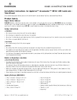
6. Remove shade screws (H) from underside of 

cage (G) and carefully lower shade (F) and 
cage (G) and set aside for later use. Remove 
and discard plastic inserts.

A

G

F

6

Hardware Used

x 2

Machine Screw

BB

Attach mounting strap (B) to outlet box (not included) 

using the existing washers and outlet box screws or 

the machine screws (BB). 

NOTE:

 If the outlet box 

screws required for your outlet box are of a different 

size than the machine screws (BB), consult with a 

licensed electrician before proceeding.

Tighten machine screws (BB) completely to secure 

mounting strap (B) to outlet box.

Turn crossbar on mounting strap (B) so the screws 

(D) are level horizontally. [Use a level (not included) 

to adjust screws (D) parallel with floor and ceiling as 

needed.] Tighten preassembled set screw, located in 

the middle of the mounting strap (B), to secure 

crossbar.


CAUTION:


The fixture must be mounted to an 

outlet box that is supported by the building structure 

and can support the weight of the fixture. Plastic 

outlet boxes are not recommended.

H

Temporarily place fixture (A) over mounting 

strap (B) to determine amount of adjustment 

necessary for screws (D); screws (D) should 

come through holes in fixture (A) just enough so 

decorative nuts (C) will fit flush against fixture 

(A) when mounted. 

Once screws (D) are adjusted, use pliers (not 

included) to tighten nuts (E) on screws (D) until 

nuts (E) touch mounting strap (B).

5.

5

Outlet Box

B

A

C

D

E

H

Outlet Box

D

B

4

Crossbar

BB

BB

Summary of Contents for WL136MW

Page 1: ...o design are trademarks or registered trademarks of LF LLC All rights reserved VR21099 Questions problems missing parts Before returning to your retailer call our customer service department at 1 888...

Page 2: ...tenance 10 Troubleshooting 10 Warranty 10 TABLE OF CONTENTS 2 A Fixture 1 B Mounting Strap 1 C Decorative Nut preassembled to 2 screw D D Screw preassembled to mounting 2 strap B E Nut preassembled to...

Page 3: ...subject to electrical shock which could cause serious injury or death DO NOT connect the bare or green insulation fixture ground wire to the black HOT current carrying wire or the white NEUTRAL house...

Page 4: ...install fixture at least 4 ft above the ground floor Before beginning assembly of product make sure all parts are present Compare parts with package contents list and hardware contents list If any pa...

Page 5: ...supply line leads DANGER Failure to disconnect power supply prior to installation may result in serious injury or death 1 Remove existing fixture and disconnect all electrical wiring 1 2 Remove two de...

Page 6: ...p B so the screws D are level horizontally Use a level not included to adjust screws D parallel with floor and ceiling as needed Tighten preassembled set screw located in the middle of the mounting st...

Page 7: ...re from outlet box using existing wire connector or wire connector AA NOTE Screw wire connectors AA on in a clockwise direction WARNING Never connect ground wire to WHITE or BLACK power supply wires W...

Page 8: ...n to the wire WARNING Make sure no bare wire or wire strands are visible after making connections Push wire connectors AA gently into outlet box Carefully push excess wiring into outlet box 9 Align ho...

Page 9: ...unting surface with silicone weather sealant not included WARNING Failure to caulk fixture mounting surface with silicone weather sealant may result in water damage in outlet box which may cause elect...

Page 10: ...y for direct incidental or consequential damages improper packaging of returned products and acts of God As some states do not allow exclusions of limitations on an implied warranty the above exclusio...

Reviews: