background image


Federal regulations require ceiling fans with light kits manufactured or imported after 
January 1, 2009, to limit total wattage consumed by the light kit to 190W.  Therefore, 
this fan is equipped with a wattage limiting device.

Questions, problems, missing parts?

 Before returning to your retailer, call or contact our 

customer service department at 

1-800-527-1292

, 8:30 a.m. - 5:00 p.m., CST, Monday - Friday.

Harbor Breeze® is a registered trademark 
of LF, LLC. All Rights Reserved.

ATTACH YOUR RECEIPT HERE

Serial Number

Purchase Date

1

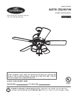
ITEM #0243307

MODEL #E-AM54AI5LKL

AUSTIN CEILING FAN

Español p. 19

E192641

Summary of Contents for E-AM54AI5LKL

Page 1: ...th a wattage limiting device Questions problems missing parts Before returning to your retailer call or contact our customer service department at 1 800 527 1292 8 30 a m 5 00 p m CST Monday Friday Harbor Breeze is a registered trademark of LF LLC All Rights Reserved ATTACH YOUR RECEIPT HERE Serial Number Purchase Date 1 ITEM 0243307 MODEL E AM54AI5LKL AUSTIN CEILING FAN Español p 19 E192641 ...

Page 2: ...eed to be returned to the factory for repairs it must be shipped in its original packaging to ensure proper protection against damage that might exceed the initial cause for return Make sure that all electrical connections comply with local codes ordinances the National Electrical Code and ANSI NFPA 70 1999 Hire a qualified electrician or consult a do it yourself wiring handbook available at Lowe ...

Page 3: ...o lead wires from the fan If your house wire is larger than 12 gauge or there is more than one house wire to connect to the two fan lead wires consult an electrician for the proper size wire connectors to use To reduce the risk of fire or electrical shock do not use the fan with any solid state speed control device or control fan speed with a full range dimmer switch To reduce the risk of fire ele...

Page 4: ...T Clip preassembled 1 U Socket Ring 3 preassembled V Hex Nut preassembled 1 W Lock Washer 1 preassembled PART DESCRIPTION QUANTITY A Downrod 2 B Canopy 1 C Mounting Bracket 1 D Yoke Cover 1 E Motor Housing 1 F Switch Housing Plate 1 G Light Kit Fitter 1 H Switch Housing 1 I Shade 3 J Blade Plate 5 K Blade Arm 5 L Blade 5 M Pull Chain Extension 2 N Candelabra Base Bulb 3 O Canopy Cover 1 PACKAGE CO...

Page 5: ...rs Bulbs Required included 3 candelabra base 40 watt max bulbs DANGER When using an existing outlet box make sure the outlet box is securely attached to the building structure and can support the full weight of the fan Failure to do this can result in serious injury or death The stability of the outlet box is essential in minimizing wobble and noise in the fan after installation is complete CAUTIO...

Page 6: ...19 A B 2 2 Check to make sure blades L are at least 30 in from any obstruction Check downrod A length to ensure blades L are at least 7 ft above the floor Fig 3 7 ft min 30 in min 3 3 Secure mounting bracket C to outlet box using screws spring washers and flat washers provided with the outlet box Fig 4 Note It is very important that you use the proper hardware when installing the mounting bracket ...

Page 7: ... shiny side toward the motor housing E Thread wires from motor housing E through downrod A 2 Hanging Ball 2 Slip downrod A into motor housing yoke align holes and re install pin S and clip T Tighten set screws and then tighten nuts Slide yoke cover D down until it rests on top of motor housing E Fig 3 Set Screw A 3 3 E T S D Set Screw T A O Remove pin S and clip T from motor housing yoke at top of...

Page 8: ...the following manner Take the lead wires and make sure that you have pulled them all the way through the top of the downrod A Start at the TOP of the ball on the downrod A and measure 8 in of lead wire and then cut the excess wire off with wire cutters Fig 4 NOTE If you do not cut back the lead wires Steps 4 and 5 are not necessary and you may proceed to Step 6 instead 4 Ball A D 4 FAN MOUNTING In...

Page 9: ...ng Connect all GROUND GREEN wires together from fan on downrod and mounting bracket to BARE GREEN wire from ceiling Fig 1B 1 FAN AND LIGHT CONTROLLED BY PULL CHAINS BLACK WHITE GROUND GREEN BARE WHITE BLUE WHITE FROM FAN 120 V Power FROM CEILING FAN CONTROLLED BY PULL CHAIN LIGHT BY WALL SWITCH WHITE BLACK BLACK WALL SWITCH GROUND GREEN BARE BLACK BLUE WHITE FROM FAN FAN 120 V Power FROM CEILING F...

Page 10: ...ses only not intended to cover all types of controls 2 Hardware Used 3 WIRING 1C FAN AND LIGHT CONTROLLED BY TWO WALL SWITCHES If you intend to control the fan and light with separate wall switches connect BLACK wire from fan to BLACK wire from the independent wall switch for the fan Connect BLUE wire from fan to the BLACK wire from the other independent wall switch for the light Connect WHITE wir...

Page 11: ...Tighten all motor screws P securely FINAL INSTALLATION 1 Locate two canopy mounting screws R on underside of mounting bracket C and remove canopy mounting screw R closest to the open end of of the mounting bracket C Partially loosen the other canopy mounting screw R Lift canopy B to mounting bracket C Place rounded part of slotted hole in canopy B over loosened canopy mounting screw R in mounting ...

Page 12: ... light kit attach switch housing H as described in Step 8 on the following page Remove one screw from fitter plate on underside of motor and loosen the other two screws Align slotted holes in switch housing plate F with loosened screws in fitter plate Twist switch housing plate F to lock and re install screw that was previously removed Tighten all screws securely Fig 4 Fitter Plate 4 E F 4 FINAL I...

Page 13: ...sly removed and tighten all screws securely with a Phillips screwdriver Fig 8 Note If you are not using the light kit please proceed to Step 11 instead of continuing with Step 9 FINAL INSTALLATION 8 F H G 8 Remove socket rings U from sockets Use these socket rings U to attach shades I to light kit fitter G Fig 9 9 I G U 9 Install three candelabra base 40 watt max bulbs N included Fig 10 Important ...

Page 14: ...g 11 NOTE This fan is remote control adaptable remote control sold separately 11 M 11 OPERATION INSTRUCTIONS 1 2 The pull chain on the switch housing H has four positions to control fan speed One pull is HIGH two is MEDIUM three is LOW and four turns the fan OFF Fig 1 The pull chain in the middle is used to turn the lights ON or OFF Fig 2 1 2 FINAL INSTALLATION 14 ...

Page 15: ...can help move stagnant hot air off the ceiling area Fig 3B 3C IMPORTANT Reverse switch must be set either completely to the RIGHT or completely to the LEFT for fan to function If the reverse switch is set in the middle position Fig 3C fan will not operate 3A 3B 3C OPERATION INSTRUCTIONS At least twice each year lower canopy B to check downrod A assembly and then tighten all screws on the fan Clean...

Page 16: ...ak in period of a few days especially when running the fan at Medium and High speeds Excessive wobbling 1 Blades L are loose 1 Tighten all blade screws AA 2 Blade arms K incorrectly 2 Re install blade arms K attached 3 Unbalanced blades L 3 Switch one blade L with a blade L from the opposite side 4 Fan not securely mounted 4 Turn power off Carefully loosen canopy B and verify that mounting bracket...

Page 17: ... warranty call our customer service department at 1 800 527 1292 for return authorization and shipping instructions so that we may repair or replace the ceiling fan Any fan or parts returned improperly packaged is are the sole responsibility of the purchaser There is no further express warranty Litex Industries disclaims any and all implied warranties The duration of any implied warranty which can...

Page 18: ...nd on page 1 A Downrod B Canopy C Mounting Bracket D Yoke Cover F Switch Housing Plate G Light Kit Fitter H Switch Housing I Shade J Blade Plate K Blade Arm L Blade M Pull Chain Extension O Canopy Cover P Motor Screw Q 5 4M M Lock Washer R Canopy Mounting Screw S Pin T Clip U Socket Ring V Hex Nut W Lock Washer AA Blade Screw BB Fiber Blade Washer CC E3 Wire Connector PART DESCRIPTION G S H F B A ...

Page 19: ...rve para limitar el vatiaje 19 ARTICULO 0243307 MODELO E AM54AI5LKL VENTILADOR DE TECHO AUSTIN Harbor Breeze es marca registrada de LF LLC Reservados todos los derechos E192641 Preguntas problemas faltan piezas Antes de regresar a la tienda llame o póngase en contacto con nuestro departamento de servicio al cliente al 1 800 527 1292 de 8 30 a m a 5 00 p m hora central de lunes a viernes ADJUNTE SU...

Page 20: ...fábrica por alguna reparación se debe enviar en su paquete original para asegurar la protección apropiada contra daños que podrían exceder la causa inicial por la cual se devolvió Asegúrese de que todas las conexiones eléctricas cumplen con los códigos y las ordenanzas locales con el Código Nacional Eléctrico NEC por sus siglas en inglés y ANSI NFPA 70 1999 Contrate un electricista calificado o co...

Page 21: ... ventilador Si el calibre del cable de la casa es superior al 12 o hay más de un cable de la casa para conectar a los cables principales del ventilador consulte con un electricista para informarse sobre el tamaño correcto de conectores para cable que se debe usar Para reducir el riesgo de incendio o un choque eléctrico no use el ventilador con ningún control de velocidad de estado sólido ni contro...

Page 22: ...ndela de seguridad 1 preensamblada PIEZA DESCRIPCION CANTIDAD A Vástago 2 B Cubierta 1 C Soporte de montaje 1 D Cubierta del yugo 1 E Bastidor del motor 1 F Placa de la caja del 1 interruptor G Conectador para el juego 1 de luz H Caja del interruptor 1 I Pantalla de vidrio 3 J Placa para la paleta 5 K Brazo para la paleta 5 L Paleta 5 M Extensión para la cadena 2 de encendido N Bombilla de base 3 ...

Page 23: ...ción eléctrica de hágalo usted mismo disponible en Lowe s y cortaalambres Bombillas necesarias incluidas 3 bombillas de base candelabro de 40 vatios máx PELIGRO Cuando utilice una caja de salida existente asegúrese de que la caja de salida esté firmemente sujetada a la estructura del edificio para que pueda sostener el peso total del ventilador El no hacer ésto puede resultar en graves daños o la ...

Page 24: ...9 2 Asegúrese de que las paletas L del ventilador queden a por lo menos 76 2 cm de cualquier obstrucción Verifique la longitud del vástago A para asegurarse de que las paletas L queden a por lo menos 2 13 m arriba del nivel del piso Fig 3 3 4 Asegure el soporte de montaje C a la caja de salida con los tornillos las arandelas de resorte y las arandelas planas provistos con la caja de salida Fig 4 N...

Page 25: ...ado de los provistos El montaje en ángulo es más adecuado para techos en ángulo o abovedados A veces se necesitarán vástagos más largos para asegurar el espacio adecuado para las paletas del ventilador Escoja el largo de vástago A que desea usar Si elige usar el vástago A de 30 48 cm quite la bola que sirve para colgar del vástago A de 15 24 cm para usar la en el vástago A de 30 48 cm Introduzca e...

Page 26: ...ra que sigue Tome los cables principales y asegúrese de que los haya jalado completamente por la parte superior del vástago A Comience en la parte SUPERIOR de la bola en el vástago A y mida 20 5 cm de cable principal y luego corte el cable en exceso con cortaalambres Fig 4 NOTA Si no va a cortar los cables principales los pasos 4 y 5 no son necesarios y se puede continuar con el paso 6 en su lugar...

Page 27: ...EGRO que corresponde al interruptor independiente Conecte el cable BLANCO del ventilador al cable BLANCO del techo Conecte todos los CONDUCTORES A TIERRA cables VERDES del ventilador en el vástago y el soporte de montaje al cable PELADO VERDE del techo Fig 1B 1A 1B NEGRO BLANCO TIERRA VERDE PELADO BLANCO NEGRO AZUL BLANCO DEL VENTILADOR 120 V cables de corriente DEL TECHO VENTILADOR VERDE VENTILAD...

Page 28: ... conduce energía eléctrica del juego de luz El cable blanco es tanto para el ventilador como para el juego de luz El cable verde o pelado es el que hace tierra VERDE 2 3 Ponga cinta aislante en cada conector para cable CC por separado como se muestra en la Fig 2 ADVERTENCIA Asegúrese de que no se vean cables pelados ni filamentos después de hacer las conexiones Coloque las conexiones verdes y blan...

Page 29: ...gujeros con ranura en la decoración para la cubierta O con las cabezas de tornillo en el fondo de la cubierta B Gire la decoración para la cubierta O a la derecha en el sentido de las agujas del reloj hasta que ya no gire Fig 1 Coloque la paleta L entre el brazo para la paleta K y la placa para la paleta J y alinee los agujeros Introduzca tres tornillos para las paletas AA junto con las arandelas ...

Page 30: ...ue ligan los dos cables Fig 5 Si NO desea utilizar el juego de luz sujete la caja del interruptor H como se describe en el paso 8 en la página siguiente 5 tapa BLANCO AZUL H Quite la tuerca hexagonal V y la arandela de seguridad W de la varilla roscada en el conectador para el juego de luz G Pase los cables del conectador para el juego de luz G delicadamente por el agujero de en medio de la caja d...

Page 31: ...nte Alinee los agujeros en la caja del interruptor H con los agujeros en la placa de la caja del interruptor F Vuelva a introducir los tornillos que se quitaron anteriormente y apriete los tornillos bien con destornillador Phillips Fig 8 Nota Si no va a utilizar el juego de luz por favor continúe con el paso 11 en vez de seguir con el paso 9 Instale las tres bombillas de base candelabro N de 40 va...

Page 32: ...ilador es adaptable para uso con control remoto a la venta por separado 11 M 11 INSTALACION FINAL 1 2 INSTRUCCIONES DE FUNCIONAMIENTO 1 2 La cadena de encendido en la caja del interruptor H tiene cuatro posiciones para controlar la velocidad del ventilador Jálela una vez para la velocidad ALTA dos veces para la velocidad MEDIA tres veces para la velocidad BAJA y cuatro veces para APAGAR el ventila...

Page 33: ...n flujo de aire descendente creando un efecto de viento refrescante Fig 3A 3B En un clima más fresco el mover el interruptor de reversa a la DERECHA producirá un flujo de aire ascendente que podrá servir para mover el aire caliente acumulado en el techo Fig 3B H 3 3A 3B 3C interruptor de reversa Baje Ia cubierta B para inspeccionar el conjunto del vástago A por lo menos dos veces al año y luego ap...

Page 34: ...on reductor de luz 3 Reemplace el control con un de gama completa aparato de control de velocidad aprobado 4 El ventilador es nuevo 4 Permita unos días para que el motor del ventilador se equilibre especialmente al usar el ventilador a velocidad media o alta Tambaleo excesivo 1 Las paletas L están flojas 1 Apriete todos los tornillos para las paletas AA 2 No se instalaron correctamente 2 Instale l...

Page 35: ...fes los cables en la caja del macho y hembra y las conexiones interruptor H tipo molex en la caja del interruptor H estén conectados bien según las instrucciones en la página 30 y 31 5 Se ha quitado el juego de luz 5 Vuelva a instalar el juego de luz original y el vatiaje sobrepasa original o ponga bombillas en los 190W permitidos haciendo el juego de luz que suman no más que se interrumpa la corr...

Page 36: ...ipos de condiciones climáticas esta garantía no cubre ningún cambio en el acabado bronce ni por la oxidación marcas la decoloración la corrosión ni el descascarillado del material Se conserva la belleza de un ventilador con acabado bronce protegiéndolo de las diversas condiciones de clima Las pantallas provistas con el ventilador no están cubiertas por la garantía Cualquier pieza defectuosa del ve...

Page 37: ... montaje D Cubierta del yugo F Placa de la caja del interruptor G Conectador para el juego de luz H Caja del interruptor I Pantalla de vidrio J Placa para la paleta K Brazo para la paleta L Paleta M Extensión para la cadena de encendido O Decoración para la cubierta P Tornillo del motor Q Arandela de seguridad 5 4M M R Tornillo para montaje de la cubierta S Clavija T Sujetador U Anillo de portalám...

Reviews: