11
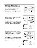
7.
Gently feed wires from light kit fitter (E) through
center hole in switch housing cap (C). Screw switch
housing (C) onto threaded rod on light kit fitter (E)
followed by lock washer (II) and hex nut (HH).
Tighten hex nut (HH) over lock washer (II) for a
secure fit. (Fig. 7)
Connect
WHITE
wire from light kit fitter (E) to
WHITE
wire from switch housing. Connect
BLACK
wire from
light kit fitter (E) to
BLUE
wire from switch housing
cap. (Fig. 7) Make sure that molex connections are
secure.
Molex
Connections
Threaded
Rod
E
C
HH
II
6.
Punch center cap out of switch housing cap (C)
with a screwdriver. (Fig. 6A)
Remove hex nut (HH) and lock washer (II) from
threaded rod at top of light kit fitter (E). Remove finial
(L), finial plate (K) and white washer from threaded
rod at bottom of light kit fitter (E). (Fig. 6B)
Save hex
nut (HH), lock washer (II), finial (L), finial plate (K)
and white washer for later use
.
Center
Cap
C
E
HH
II
L
K
White
Washer
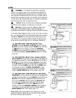
5.
If you wish to USE the light kit
, remove three
screws from switch housing cap (C) and remove
switch housing cap (C) from switch housing. Locate
BLUE
and
WHITE
wires in switch housing labeled
“FOR LIGHT” and remove plastic from these two
wires. (Fig. 5) Continue with Step 6.
If you do NOT wish to use the light kit
, skip to Step
11 to attach pull chain extension (J) and complete
installation.
A
C
Switch
Housing
FINAL INSTALLATION
Fig. 5
Fig. 6A
Fig. 6B
HH
II
Hex Nut x 1
Lock Washer x 1
Hardware Used
Fig. 7
HH
II
Hex Nut x 1
Lock Washer x 1
Hardware Used


