background image

7

Lowes.com/harborbreeze

INITIAL INSTALLATION

1.  Turn off the circuit breakers and the wall switch to the 

fan supply line leads.


DANGER:

 Failure to disconnect the power 

supply prior to installation may result in serious injury 

or death.

1

2.  Determine the mounting method to use.

Helpful Hint:

 Standard mounting is best suited for 

ceilings 8 ft. or higher. For taller ceilings you may want 

to use a longer downrod (not included).  
Closemount-style mounting is more suitable for 

ceilings lower than 8 ft. high. 
Flushmount installation is not available for this item.
Angle-style mounting is best suited for angled or 

vaulted ceilings. A longer downrod is sometimes 

necessary to ensure proper blade clearance.

Important:

 If using the angle mount, check to ensure 

the ceiling angle is not steeper than 16°.

2

Standard Mounting

Flushmount 

Closemount 

Angle Mounting

3.  Ensure the blades (J) will be at least 30 in. from any 

obstructions. Also check the downrod (A) length to 

ensure the blades (J) will be at least 7 ft. above the 

floor.

A

7 ft.
Minimum

30 in. 

Minimum

3

A

J

Summary of Contents for BUILDER'S SERIES 40698

Page 1: ...nt at 1 800 643 0067 8 a m 6 p m EST Monday Thursday 8 a m 5 p m EST Friday ATTACH YOUR RECEIPT HERE Serial Number _________________________ Purchase Date _________________________ Harbor Breeze is a...

Page 2: ...Safety Information 5 Preparation 6 Initial Installation 7 Standard or Angle Mounting Instructions 9 Closemount Instructions 11 Wiring 12 Final Installation 13 Operating Instructions 15 Care and Mainte...

Page 3: ...y Cover preassembled to the Canopy D 1 G Motor Assembly 1 H Switch Housing preassembled to the Motor Assembly G 1 I Blade Arm 5 J Blade 5 K Blade Balance Kit 1 L Motor Screw preassembled to the Motor...

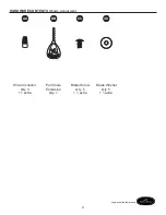
Page 4: ...4 Lowes com harborbreeze HARDWARE CONTENTS shown actual size Wire Connector Qty 3 1 extra Pull Chain Extension Qty 1 Blade Screw Qty 5 1 extra Blade Washer Qty 5 1 extra AA BB CC DD H arbor Bree z e...

Page 5: ...shock or personal injury mount the fan to an outlet box marked ACCEPTABLE FOR FAN SUPPORT and use the mounting screws provided with the outlet box Most outlet boxes commonly used for the support of l...

Page 6: ...at all parts are present Compare all parts with the package contents list and hardware contents list If any part is missing or damaged do not attempt to assemble the product After opening the top of t...

Page 7: ...Closemount style mounting is more suitable for ceilings lower than 8 ft high Flushmount installation is not available for this item Angle style mounting is best suited for angled or vaulted ceilings...

Page 8: ...proper hardware when installing the mounting bracket E as it will support the fan Important If using the angle mount ensure the open end of the mounting bracket E is installed facing the higher point...

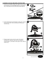
Page 9: ...t screws O in the yoke at the top of the motor assembly G 1 2 Insert the downrod A through the canopy D Thread the wires from the motor assembly G through the downrod A 3 Slide the downrod A into the...

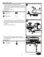
Page 10: ...insulation from the end of the white wire Twist the stripped ends of each strand of wire within the insulation with pliers not included Repeat this step for black blue and green wires Important If you...

Page 11: ...closemount screws M from the top of the motor assembly G Align the canopy D with the holes in the top of the motor assembly G then re install the Phillips head closemount screws M to secure the canop...

Page 12: ...eutral supply wire Connect the Black and Blue wires from the fan to the Black hot supply wire Secure all wiring connections together with wire connectors AA Note The Black fan wire is hot power for th...

Page 13: ...cket E Place the keyholes of the canopy D onto the mounting bracket screws N and rotate the canopy D clockwise 2 Secure the canopy D with the mounting bracket screws N previously removed Step 4 page 8...

Page 14: ...ach blade J Hardware Used CC Blade Screw x 5 Blade Washer x 5 4 Install the blade arm I to the underside of the motor assembly G with motor screws L previously removed Step 6 page 8 Tighten with Phill...

Page 15: ...r comfort Note Wait for the fan to stop before moving the reverse switch 2a In warmer weather push the reverse switch down to display a sun icon which will result in downward airflow creating a wind c...

Page 16: ...ker is blown 4 There is a faulty wire connection 1 Firmly push the reverse switch completely up or down 2 Turn the power on at wall switch 3 No electricity or fuse or breaker is blown 4 Turn the power...

Page 17: ...ll screws that hold the fan blades to the blade arms and the blade arms to the motor 2 Switch one blade with a blade from the opposite side Or balance the fan using the blade balance kit K 3 Turn off...

Page 18: ...id Due to varying climate conditions this warranty does not cover any changes in brass finish including rusting pitting corroding tarnishing or peeling Brass finishes of this type give their longest u...

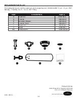
Page 19: ...r replacement parts call the customer service department at 1 800 643 0067 8 a m 6 p m EST Monday Thursday 8 a m 5 p m EST Friday PART DESCRIPTION PART A Downrod 0593748 A D Canopy 0593748 D E Mountin...

Reviews: